Before comparing an existing bored-lock preparation with a product drawing, identify backset, door thickness, cross-bore diameter, and edge-bore diameter separately. They describe different features. A correct conversion cannot make an edge-to-centerline distance comparable with a hole diameter, and four matching dimensions alone cannot establish complete lock compatibility.
This illustrated worksheet explains how to collect those measurements and carry them into the converter and dimensional comparison tool. The completed examples below are hypothetical measurements, not a drilling pattern or product specification.
Find each measurement on the door
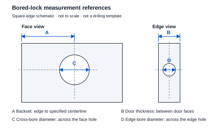
| Dimension | Start and end references | Common mistake to avoid |
|---|---|---|
| A: Backset | Specified door-edge reference to specified lock centerline; the cross-bore centerline in this sketch | Measuring to the near edge of the hole |
| B: Door thickness | One door face to the other, at a recorded location | Substituting cylinder length or handle projection |
| C: Cross-bore diameter | Across the opening through the door face, passing through its center | Calling this distance the backset |
| D: Edge-bore diameter | Across the opening entering from the door edge | Assuming it is the same diameter as the face bore |
For a beveled edge, faceplate, or special lock, use the actual manufacturer’s drawing to locate the required edge reference. Do not apply an assumed bevel correction. Record how skins, cladding, and finishes affect the thickness measurement. If a hole is oval or damaged, retain its actual outline and several measurements; a single ideal diameter may be inadequate.
Collect a traceable record
- Identify the door location and the exact hardware manufacturer, model, and series being considered.
- Obtain the applicable drawing or installation instructions. Record its revision and page or figure number.
- Mark the measurement references and note the instrument, resolution, date, and unit.
- Record the measured values separately from the drawing’s required values. Obtain missing requirements before making a comparison.
- Keep irregularities and additional preparation features with the record, including faceplate recesses, mounting holes, reinforcement, and strike details.
The following completed measurement set shows the distinction between dimensions. It does not assert that a particular product requires or accepts these values.
| Recorded dimension | Original inch measurement | Exact decimal inches | Exact millimeters |
|---|---|---|---|
| Backset, specified edge to cross-bore centerline | 2 3/8 in | 2.375 in | 60.325 mm |
| Thickness between the two identified faces | 1 3/4 in | 1.75 in | 44.45 mm |
| Cross-bore diameter through the face | 2 1/8 in | 2.125 in | 53.975 mm |
| Edge-bore diameter | 1 in | 1 in | 25.4 mm |
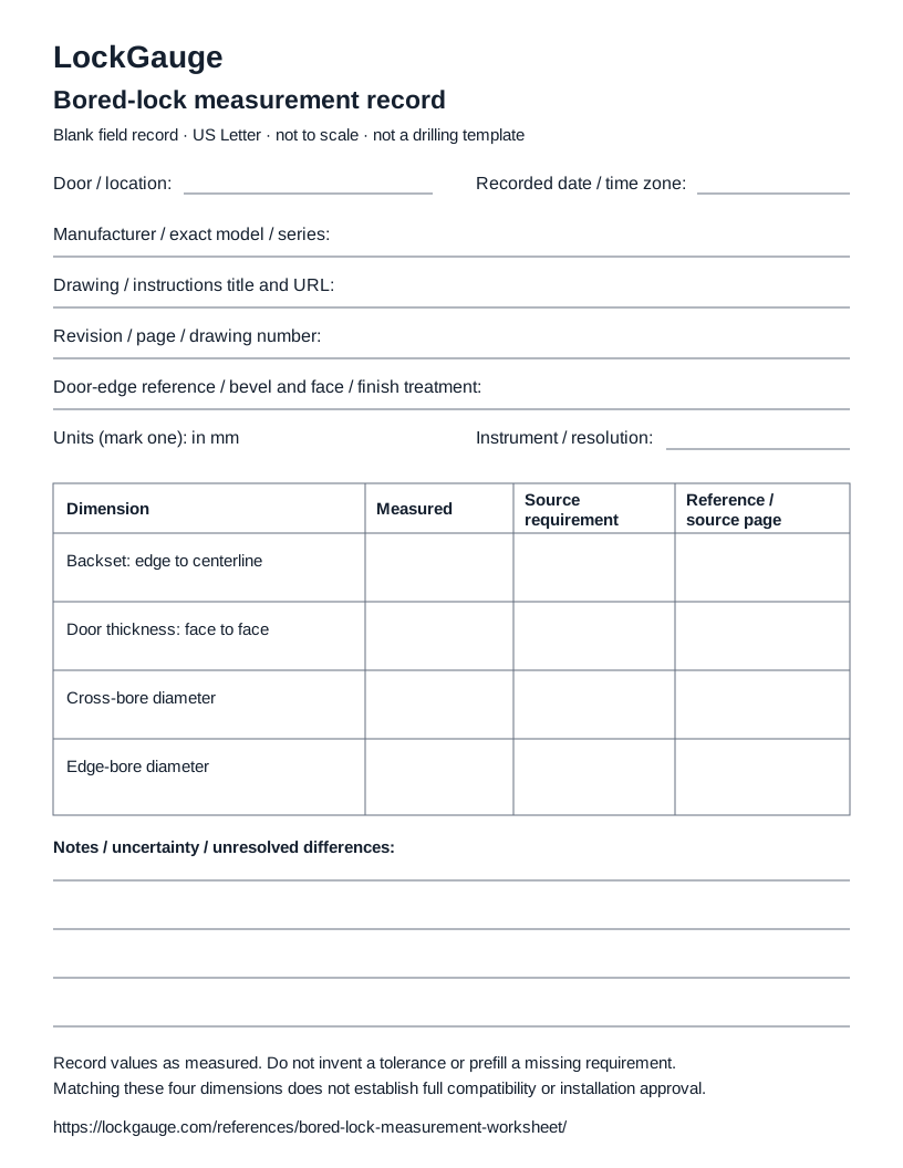
For a paper field record, download the blank US Letter measurement record. Its empty fields are for your measurements. It is a recording sheet, rather than a scale template, and this page does not save entries online.
Worked example: convert the recorded backset
Inputs: backset 2 3/8, inches selected, three decimal places in the converter.
2 + 3/8 = 19/8 = 2.375 in
(19/8) × 25.4 = 60.325 mm
Result: 2.375 in = 60.325 mm, exact for the entered number. At two decimal places, half-up rounding displays 60.33 mm. Keep the original value when checking a requirement; the rounded display is not a tolerance.
Inch fields accept decimals, fractions such as 3/8, and mixed numbers such as 2 3/8. Millimeter fields accept decimals. Enter numbers without unit suffixes. Negative lengths, missing values, and zero denominators are invalid; measurement uncertainty is not supplied by the conversion.
Worked example: compare the same dimension and reference
Suppose a separate hypothetical drawing target is 2 3/4 in, measured from exactly the same edge reference to the same centerline. In dimensional comparison, enter measured 2 3/8, target 2 3/4, inches for both, and describe that shared reference. Leave the optional limits unused unless you have an actual allowable interval.
Difference = target − measured
2.75 − 2.375 = +0.375 in
0.375 × 25.4 = +9.525 mm
Result: the target is 0.375 in farther from the reference edge. This says nothing about whether the existing hole may be moved or enlarged. If you supply limits, both endpoints are required and the measured value is compared with the inclusive interval. The target does not create its own allowable range.
Conclusion
Keep all four dimensions, their physical references, and the source drawing together. Convert units when needed, then compare like quantities. Confirm the remaining product, door-construction, fastener, function, and assembly requirements before deciding whether hardware can be installed.
Sources
Schlage’s door-preparation checklist distinguishes cross bore, edge or latch bore, backset, and door thickness in residential bored-lock preparation. Its product-oriented sizes are not universal requirements. NIST’s length reference supplies the exact inch-to-millimeter relationship. The illustration and worked measurements here are original explanatory material.