Torque, pressure moment, actuator stroke, and spring stiffness describe different parts of a door mechanism. Choose the model from the load or geometry you can actually specify. Keep its conditions with the result: a correct torque does not determine actuator stroke, and a correct stroke does not establish an actuator’s force or mounting suitability.
Start with the quantity you know
| Known information | Tool | Output |
|---|---|---|
| Force, application radius, included force angle | Static torque | One moment magnitude |
| Moment, radius, and nonzero moment-arm angle | Static torque, inverse force mode | The force magnitude required by that stated geometry |
| Uniform net pressure on a rectangular face | Door pressure moment | Resultant and moment about its vertical edge |
| Fixed anchor and rotating pin position | Actuator stroke | Pin distances and geometric stroke over the interval |
| Linear torsional stiffness and winding | Ideal torsion spring | Initial/final resisting torque and added energy |
A load source and direction must be established before calculating its moment. An attachment layout must be established before calculating its travel. None of these tools infers the actual resistance of an installed door.
Calculate the moment arm, not just radius times force
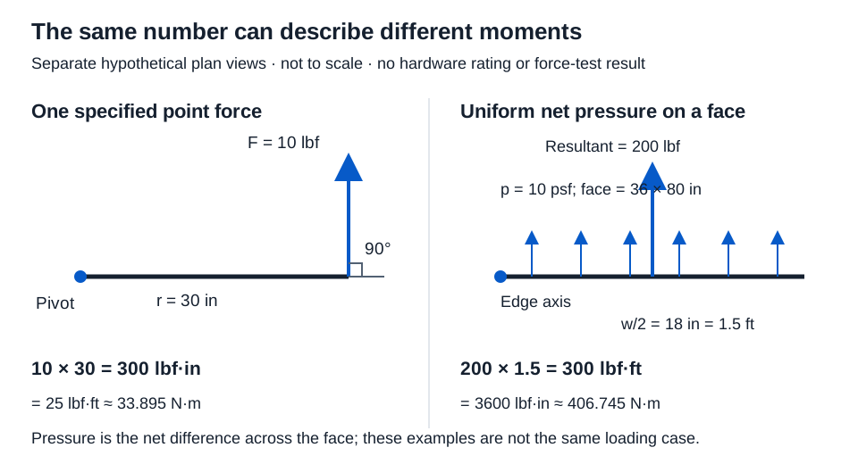
In static torque, choose forward torque mode, lbf, and inches. Enter a hypothetical 10 lbf force, 30 in radius, and 90° included angle between the radius and force.
Torque magnitude τ = rF sin φ
τ = 30 × 10 × sin 90° = 300.000 lbf·in
300/12 = 25.000 lbf·ft
Using the exact force and length relationships, that is 33.895 N·m after three-decimal rounding. The included force angle is not automatically the door opening angle. At a 30° force angle, the same force and radius give 30 × 10 × 0.5 = 150.000 lbf·in.
For inverse mode, select the torque unit and enter 300 lbf·in, 30 in, and the included angle:
| Included angle φ | Effective moment arm r sin φ | Force for 300 lbf·in |
|---|---|---|
| 90° | 30 in | 300/30 = 10.000 lbf |
| 30° | 15 in | 300/15 = 20.000 lbf |
| 0° or 180° | 0 in | Inverse is undefined; input is rejected |
The forward model supports 0–180° and can return zero moment at the endpoints. Inverse mode requires an angle strictly between them. Radius must be positive; force or specified moment may explicitly be zero. The tool reports one magnitude, without net torque, capacity, or an opening-force compliance determination. OpenStax’s torque derivation explains the sine relationship.
Keep pressure units and torque units visible
For a different hypothetical case, select inches and psf in door pressure moment. Enter 36 in width, 80 in height, and 10 psf net pressure normal to the face. Use the pressure difference across the door, not atmospheric pressure.
Area = 36 × 80/144 = 20 ft²
Resultant = pressure × area = 10 × 20 = 200 lbf
Edge-axis moment = resultant × half-width = 200 × 1.5 = 300 lbf·ft
This equals 3600 lbf·in, twelve times the 300 lbf·in point-force example. The calculator’s moment displays 300.000 lbf·ft, or 406.745 N·m. Width and height must be positive; net pressure may be zero. The model does not obtain a site design pressure or calculate changing open-door aerodynamics.
Examine actuator length through the whole movement
Put the door pivot at (0,0) and the moving pin initially at (r,0). In actuator stroke, enter radius, fixed-anchor x/y coordinates, and final counterclockwise angle in one plane and unit.
For r = 10 in, fixed anchor (0,10) in, and final angle 180°:
L(θ) = √[(10 cos θ − 0)² + (10 sin θ − 10)²]
At 0° and 180°, length is √200 ≈ 14.142 in. At 90°, the points coincide and length is zero. Therefore:
Geometric stroke = interval maximum − interval minimum = √200 − 0 ≈ 14.142 in
Subtracting endpoint lengths would incorrectly give zero. The tool evaluates interior extrema as well as endpoints. Its supported interval is 0–180°, radius must be positive, and the fixed anchor cannot equal the pivot.
Zero pin distance is a defined geometric boundary, but it exposes an unusable position for a real actuator body. Body length, joint articulation, interference, mounting strength, force, and dynamic behavior still require a product-specific assessment. Use the coordinate atlas to preserve the attachment references.
Convert spring winding to radians before calculating
For an ideal torsion spring, enter stiffness 10 N·m/rad, preload 0°, and additional winding 90°. Stiffness is per radian even though the angle controls use degrees.
Final winding θ = 90 × π/180 = π/2 rad
Final torque = kθ = 10π/2 ≈ 15.708 N·m
Added energy = k(θ² − 0²)/2 = 10(π/2)²/2 ≈ 12.337 J
Positive stiffness is required. Preload and additional winding are each supported from 0–360°, as software limits rather than product ratings. The model assumes linear stiffness and additional winding in the same direction; it omits friction, hysteresis, fatigue, and real spring travel limits.
Carry the assumptions into the next decision
Retain original values, units, load sources, application points, angle intervals, and omitted effects on the mass and force record. Results display three decimals after calculation; trigonometric values are approximations and display rounding is not a design allowance.
Use actual hardware data to compare the relevant quantity with the product’s operating and mounting conditions. Do not combine unrelated moments, substitute stroke for force, or treat one scalar result as a complete closer, actuator, or hinge selection.