Choose a motion model by the quantity you need to find. The arc traveled by one point, the plan area swept by a thick leaf, and the span remaining beside a door are different quantities. Start with the actual mechanism and references, then choose a model whose inputs describe them.
Match the mechanism before entering dimensions
Sketch the pivot or track, opening boundaries, leaf outline, and any obstacle in one coordinate system. Name the viewing plane and units. Mathematical counterclockwise rotation does not identify a door’s handing; that requires the manufacturer’s viewpoint and swing convention.
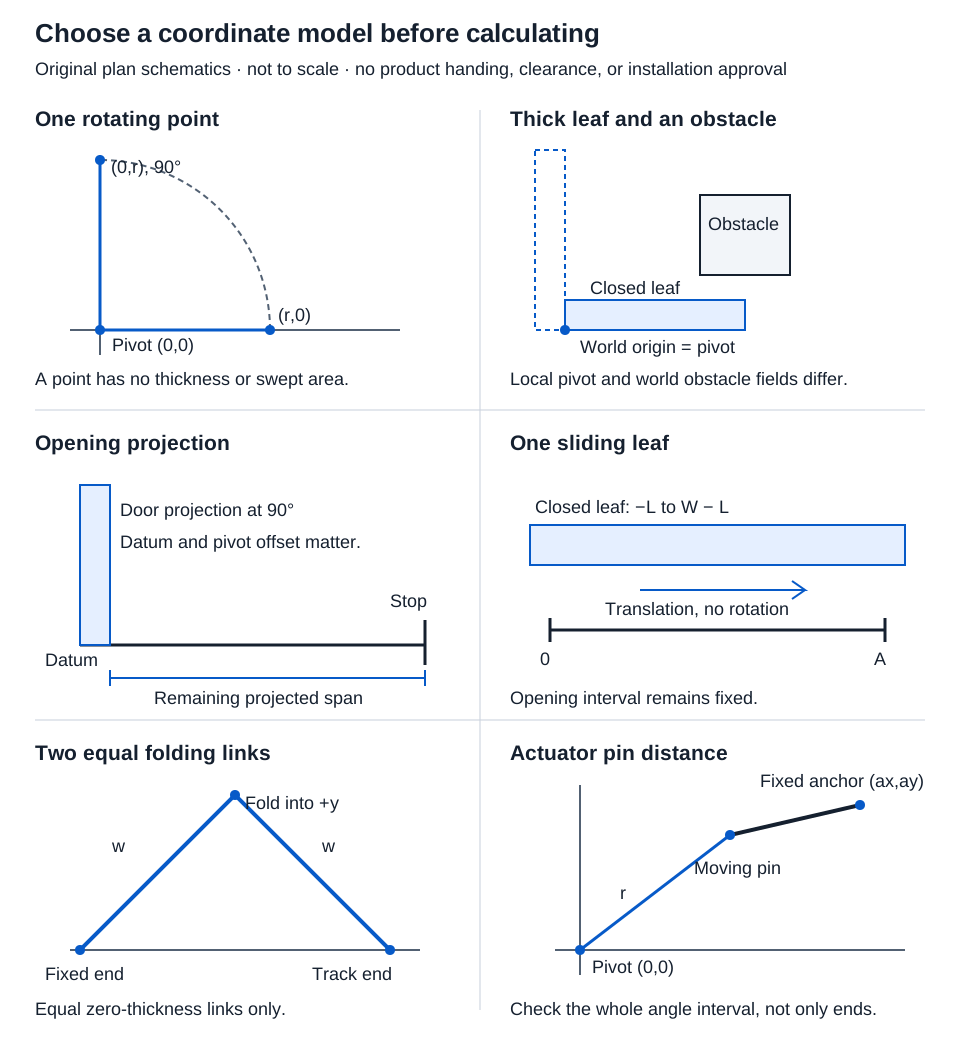
| Question | Tool | Main boundary of the result |
|---|---|---|
| Where does one point move? | Door swing geometry | Fixed-radius point, without thickness |
| Does a thick leaf overlap a specified obstacle in plan? | Door sweep obstacle | One rectangular leaf and one rectangular obstacle |
| What span remains beyond the leaf’s projection? | Opening projection | One-sided projection using a defined datum |
| How far must a leaf or pair translate? | Sliding travel | Horizontal intervals, without track or hanger design |
| How do two equal ideal folding panels move? | Equal-panel bifold | Equal zero-thickness links with a constrained endpoint |
Calculate a point’s coordinates, chord, and arc separately
In door swing geometry, select inches and enter a hypothetical radius 36 in and angle 90°. The initial point is at (36,0) in with the pivot at the origin. Rotation is counterclockwise toward positive y.
x = r cos θ = 36 cos 90° = 0 in
y = r sin θ = 36 sin 90° = 36 in
Chord = 2r sin(θ/2) = 72 sin 45° = 36√2 ≈ 50.912 in
Arc = rθ = 36 × π/2 ≈ 56.549 in
The arc formula uses radians. The chord is straight endpoint displacement; the longer arc follows the circular path. OpenStax’s rotational-variable explanation supports this distinction.
Radius must be positive and the supported angle is 0–180°. The point model cannot determine collision or passage width. Its numerical results display three decimals after calculation.
Include the full leaf when thickness matters
For a plan-view obstacle check, enter positive leaf width and thickness, local pivot coordinates, fixed obstacle bounds relative to the world pivot, and the final angle. The sweep tool checks the interval from closed to that angle. Do not enter obstacle positions from an unrelated drawing origin.
Contact counts as intersection under the numerical model. The displayed coordinate comparison allowance handles numerical comparisons; it is not a required installation clearance. A plan overlap at different heights may not represent physical contact. Conversely, omitting a handle, closer, or other projecting part can hide a real collision.
Opening projection answers a narrower question. For a hypothetical 36 in opening and leaf, 1.75 in thickness, local pivot (0,1.75) in, zero axis offset, and 90°:
Projection = axis offset + (width − px) cos θ + py sin θ
Projection = 0 + 36 × 0 + 1.75 × 1 = 1.750 in
Remaining span = max(0,36 − 1.75) = 34.250 in
At 0°, the same leaf projects 36 in and leaves zero span. Opening projection supports 0–90° and a pivot within the entered leaf. It does not report width compliance. The Access Board guide describes stop-to-door-face measurement at 90°; actual hardware, measurement conditions, and other applicable requirements remain separate.
Work sliding travel from fixed opening coordinates
For a single sliding leaf, select single-leaf mode and enter 36 in opening, 40 in leaf, 2 in left overlap, rightward motion, and 20 in travel.
The opening is [0,36]; the closed leaf is [−2,38]. After translation it is [18,58]. Its intersection with the opening is [18,36], so covered width is 18 in and uncovered width 18.000 in. Full-clear rightward travel is 36 + 2 = 38.000 in.
For a pair, enter a 72 in opening, 40 in per leaf, 2 in outer overlap per side, and 20 in outward travel per leaf:
| Leaf | Closed interval (in) | After outward travel (in) |
|---|---|---|
| Left | [−2,38] | [−22,18] |
| Right | [34,74] | [54,94] |
The closed meeting overlap is 4 in. The resulting central opening is 54 − 18 = 36.000 in. Each leaf needs 38.000 in total outward travel to clear fully. The tool permits independent travel values; it does not infer a synchronized mechanism. Track length, usable hanger travel, pockets, and stops must be checked separately.
Recognize the limits of an ideal fold
For 18 in equal links and 60°, enter those values in equal-panel bifold:
Track endpoint = 2w cos θ = 36 × 0.5 = 18.000 in
Fold depth = w sin θ = 18 × √3/2 ≈ 15.588 in
Retraction = 2w(1 − cos θ) = 18.000 in
The supported angle is 0–90°. At the ideal 90° endpoint, zero-thickness links coincide; a real folded door does not occupy zero width. Actual thickness, joints, carriage positions, and overlaps can change the envelope.
Keep the result attached to its geometry
Use the coordinate atlas to retain the model, axes, original inputs, angle interval, and parts omitted. Conversion uses exactly 25.4 mm per inch; three-decimal displays do not create clearance tolerances. A successful point, interval, or rectangle calculation closes that geometric question. Use actual installation drawings to resolve the remaining space, hardware, and assembly requirements.