Exact unit relationships
A calculator result is meaningful only when its unit and measurement reference remain clear. Use the illustrated references above for the task-specific geometry, input steps, tables, and examples. This overview explains the common unit definitions and how to distinguish an exact calculation from an approximate model or a product requirement.
| Quantity | Exact relationship | Typical use |
|---|---|---|
| Length | 1 in = 25.4 mm | Convert a door or hardware dimension |
| Length | 1 ft = 12 in = 0.3048 m | Convert a cable run, volume dimension, or lever arm |
| Mass | 1 lb = 0.45359237 kg | Express the same mass in two units |
| Force | 1 lbf = 4.4482216152605 N | Convert an applied force or stated weight force |
The foot used here is the international foot, not the historical U.S. survey foot. Mass in lb or kg is different from force in lbf or N. Do not paste a mass into a force field merely because the familiar term “weight” appears in both contexts.
NIST’s SI length reference supports the inch definition. NIST SP 811 Appendix B.9 gives conversion factors; footnote 22 supplies the exact pound-mass factor and footnote 23 identifies the pound-force relationship under standard gravity, 9.80665 m/s². These definitions do not determine the uncertainty of a measured dimension or force.
Worked example: keep the whole measurement
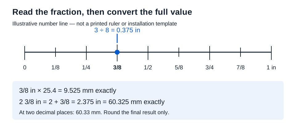
In the inch and millimeter converter, select inches and enter 2 3/8 without a unit suffix:
2 + 3/8 = 2.375 in
2.375 × 25.4 = 60.325 mm exactly
A three-decimal display is 60.325 mm; a two-decimal half-up display is 60.33 mm. Retain 60.325 mm for later arithmetic rather than treating the rounded display as the original input. The fraction chart provides exact values in 1/64 in steps, and explains values between rows.
Model formulas
The converter and dimensional comparison tools represent entered fractions and decimals as exact rational values before display rounding. The comparison uses target minus measured:
Difference = target − measured
For target 2.75 in and measured 2.375 in, the difference is +0.375 in = +9.525 mm. The positive sign means the target is larger. It is not an instruction to move a bore or remove material. A shared dimension, direction, and physical reference are required.
Other tools use explicitly bounded models. For a uniform rectangular solid, volume = width × height × thickness and mass = volume × supplied density. The geometry is exact for that ideal shape; whether the shape and density represent an actual fabricated door is a separate question. The mass and hinge-input reference shows how to keep those assumptions with the estimate.
Rotation and force models
The point swing calculator follows one point from (r,0) around a fixed pivot: x = r cos θ, y = r sin θ, chord = 2r sin(θ/2), and arc = rθ, with θ in radians. These relationships do not include door thickness or an obstacle. OpenStax §10.1 explains angular variables and arc travel. Use the motion atlas to choose among point, rectangle, projection, sliding, and folding models.
The static torque tool uses τ = rF sin φ for the magnitude of the moment from one force. φ is the angle between the pivot-to-force radius and the force, rather than automatically the door’s opening angle. The inverse force calculation requires a nonzero moment arm. OpenStax §10.6 supports that relationship. No net-force, closer-capacity, or compliance result is inferred.
Trigonometric results are numerical approximations displayed to three decimals. Intermediate values are not display-rounded. Keep the model conditions beside the result, rather than treating the number’s decimal places as evidence of physical accuracy.
Access-control DC models
Choose an electrical boundary before adding current or power. A converter’s output current belongs at its output voltage; its input current belongs in a source-side budget. The boundary and time reference gives complete simultaneous-load, converter, heat, and chronological charge examples.
| Task | Governing relationship | Required condition |
|---|---|---|
| Simultaneous load budget | Total current = sum of quantity × each current; P = VI | One stated voltage and defined simultaneous scenario |
| Equal two-wire drop | R_loop = 2Lr; drop = I R_loop | One-way L, single-conductor r, one stated far-end current |
| Converter accounting | P_input = P_output/efficiency | Efficiency at the actual operating point |
| Ideal constant-current charge | Q = It or t = Q/I | Same battery-side boundary, A, Ah, and decimal hours |
| Chronological timeline | Q = sum of I × hours; energy = sum of V × I × hours | Nonoverlapping whole-system phases |
For a hypothetical 24 V, 1 A, 100 ft one-way run with 10 Ω/1,000 ft per conductor, each conductor has 1 Ω, so the loop has 2 Ω. Drop is 2 V, load-end voltage 22 V, and wire loss 2 W. The single-conductor versus loop reference shows the full calculation and the different branch-network input representation.
A nonpositive load-end value means the stated-current operating point is unusable there. A positive value alone does not establish device operation. Resistance and device data must apply to the actual construction, temperature, state, and voltage conditions. No generic wire table, ampacity threshold, reserve percentage, or product operating range is inferred.
OpenStax Volume 2 §9.4, §9.5, and §10.2 support the Ohm’s law, power, and series-resistance relationships. §9.1 defines current as charge per time. Ah is charge, rather than Wh energy; neither a nominal Ah label nor an ideal quotient guarantees runtime.
Measurement references
Give every measurement a quantity name, unit, start and end references, and direction. The applicable product drawing determines any special reference. The bored-lock worksheet illustrates the four separate preparation measurements and supplies completed conversion examples.
Door preparation
Backset runs from the specified door-edge reference to the specified lock centerline. In a typical bored-lock face view, that is the cross-bore centerline. Door thickness is measured between the two door faces, with the measurement location and treatment of finishes identified. Cross-bore diameter describes the opening through the face; edge-bore diameter describes the opening from the edge. Neither diameter is a backset.
For beveled edges and special faceplates, follow the actual drawing. Do not add an assumed bevel compensation to a backset. Irregular openings may need several measurements and an outline rather than a single ideal diameter.
Hardware identity
A cylinder is an assembly; a keyway is the key-entry profile. Matching a keyway does not prove cylinder, cam, tailpiece, or complete-lock interchangeability. Keep exact model, series, revision, and configuration with any compatibility evidence.
Handing needs a viewpoint
Record the observation side, hinge side, swing, and manufacturer’s convention. A bare left/right label is insufficient. Mathematical counterclockwise rotation is a coordinate convention, not a handing determination.
Rounding and ranges
Half-up display rounding sends an exact tie away from zero. At three decimal places, −0.0005 in displays as −0.001 in. A small nonzero value may display as zero while its original sign and value remain in the calculation.
Dimensional comparison checks the measured value against both supplied interval endpoints, including the endpoints. With lower 2.4 in and upper 2.5 in:
| Measured input (in) | Three-decimal display (in) | Status against 2.4–2.5 in |
|---|---|---|
| 2.49999 | 2.500 | Within |
| 2.5 | 2.500 | Within, at upper endpoint |
| 2.50001 | 2.500 | Above |
The three displays look identical, but the range decisions differ correctly. The tool never invents a tolerance. Supply both limits when using the optional interval; a target alone does not create an allowable range. Repeated readings and chain bounds explains why observed variability and documented absolute bounds must also remain separate.
Product and code evidence
For an installation decision, obtain the current manufacturer’s dimension drawing and instructions for the exact hardware and door configuration. Check the whole preparation, mounting, fasteners, reinforcement, and function. General geometry tools do not contain a product compatibility database.
Standards are separate checks
ANSI/BHMA grades, UL certification, fire-door suitability, accessibility, and egress requirements involve different evidence. Applicability depends on the actual product or assembly, standard edition, jurisdiction, and adopted requirements. A component marking or one passing dimension does not establish complete installation approval. None of these calculators returns such approval.
Reading a source
Retain the publisher, document title and URL, exact model or series, revision, relevant page or figure, units, date checked, and supported claim. Resolve conflicting dimensions against the applicable source before relying on either. A source’s availability or a search excerpt is not a substitute for reading the relevant content.
Conclusion
Choose a model that fits the task, preserve original inputs and references, and interpret the result within its stated conditions. Use the task guides for the workflow and the tool directory for the calculation. Keep exact conversion, numerical approximation, measured uncertainty, and product requirements distinct throughout.