A door-hardware template needs two independent checks: it must be the right drawing, and its printed or transformed geometry must match that drawing. Correct arithmetic cannot repair a template for the wrong hardware, viewing side, or door configuration. This reference shows how to verify scale, preserve coordinate references, and check a calculated layout before using it.
Identify the template and the datum
Obtain the current template for the exact manufacturer, model or series, and installation configuration. Keep the original URL or document, revision, page, viewing side, door-edge reference, and printing instructions with your record. A datum is the reference point, line, or plane from which dimensions are located. Mark it explicitly instead of assuming that a paper edge or cropped image boundary is the origin.
Verify printed scale in both directions
Use the print-scale calibration calculator for one stated reference at a time. Enter its intended length, measured printed length, common unit, and current print percentage. Both lengths and the current percentage must be positive. The calculator reports a correction; you must reprint and measure the resulting sheet.
Example inputs: intended reference 10 in, measured print 9.8 in, current setting 100%.
Required size multiplier = 10/9.8 = 1.020408163…
Next scale setting = 100 × 10/9.8 = 102.0408163…%
Measured size error = (9.8 − 10)/10 × 100 = −2%
Displayed results: 1.020408×, 102.041%, and −2.000%. The signed printed-length difference is −0.200 in. Keep the unrounded ratio for analysis; printer controls may offer coarser increments and may apply additional scaling.
| Hypothetical reference | Intended length | Measured print | Required size multiplier | Interpretation |
|---|---|---|---|---|
| Horizontal | 10 in | 9.8 in | 1.020408… | Uniform enlargement needed for this line |
| Vertical, matching scale error | 5 in | 4.9 in | 1.020408… | Same ratio supports a uniform correction |
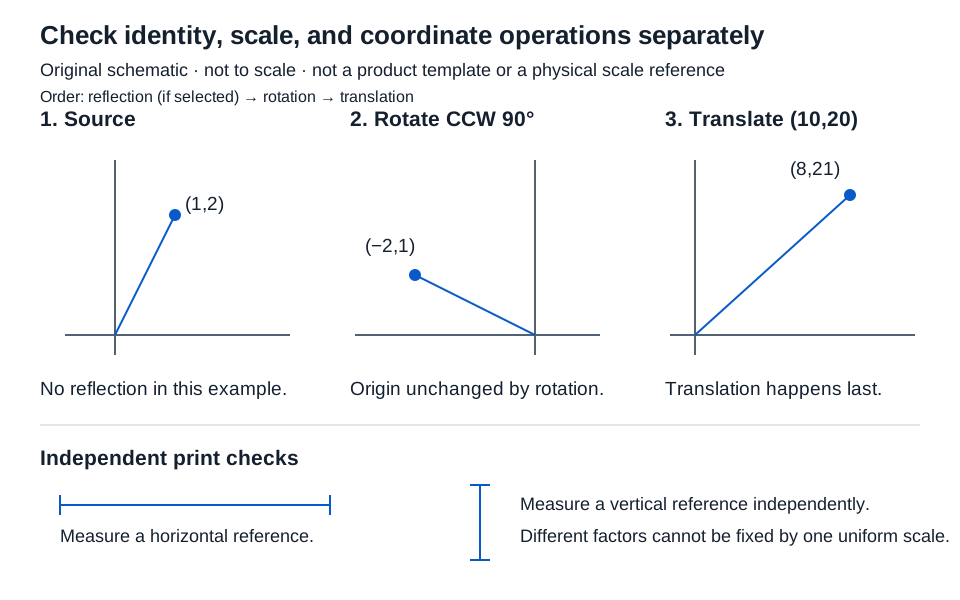
| Vertical, different scale error | 5 in | 5 in | 1 | One percentage cannot satisfy this and the horizontal line |
Check references in both axes and additional points away from the origin. If the ratios disagree, investigate cropping, image distortion, printer settings, or the source file. Do not choose whichever line looks closest or invent an acceptable error. The actual template instructions control the required verification.
Apply coordinate operations in the supported order
The template coordinate calculator performs reflection, then rotation, then translation. Select one common unit, describe the origin and positive axes, enter one x, y pair per line, and select the required reflection. Positive rotation is counterclockwise; signed angles from −360° through 360° are supported.
Reflection across the x-axis reverses y. Reflection across the y-axis reverses x. After reflection, the rotation formulas are:
x_rotated = x cos θ − y sin θ
y_rotated = x sin θ + y cos θ
Then add the x and y translations. Translation changes location without changing spacing; rotation changes orientation. Reflecting and rotating in a different order can produce different coordinates.
Worked example: rotate a point, then move it
Inputs: point (1, 2) in; no reflection; rotation 90°; translation (10, 20) in; datum described as origin at the marked corner, +x right, +y up.
At 90°, cosine is 0 and sine is 1:
x_rotated = 1 × 0 − 2 × 1 = −2 in
y_rotated = 1 × 1 + 2 × 0 = 1 in
Final point = (−2 + 10, 1 + 20) = (8, 21) in
Displayed result: (8.000, 21.000) in, or (203.200, 533.400) mm. The tool handles cardinal rotations exactly internally; other angles use numerical trigonometry. Both display to three decimal places. It supports 1–50 point pairs; coordinate and translation magnitudes are limited to 1,000,000,000 in, a numeric software bound rather than a practical layout range.
Use spacing tools only when the pattern calls for them
For an explicitly equal straight pattern, equal hole spacing needs the span, both end offsets, and 2–100 centers. With 80 in, 10 in at each end, and 4 centers:
Interval = (80 − 10 − 10)/(4 − 1) = 20 in
The center coordinates are 10, 30, 50, and 70 in from the starting reference. Four centers create three intervals. For a circular pattern, bolt-circle layout instead uses the circle center, diameter, count, starting angle, and direction. Neither tool infers an irregular manufacturer pattern.
Conclusion
Verify document identity, then scale, then the datum and calculated points. Check independent distances and locations against the original drawing before transferring a layout to an assembly. These examples follow uniform scaling and planar coordinate geometry, with exact unit conversion; they do not establish permission to drill or modify hardware.