An offset opening may fit inside a larger circle yet remain partly exposed beneath a rectangular cover. Those are different geometric questions. Use this reference to identify the actual outlines, measure their relative centers, and interpret either circular containment or rectangular coverage without treating a positive margin as complete hardware fit.
Put both outlines in one plane
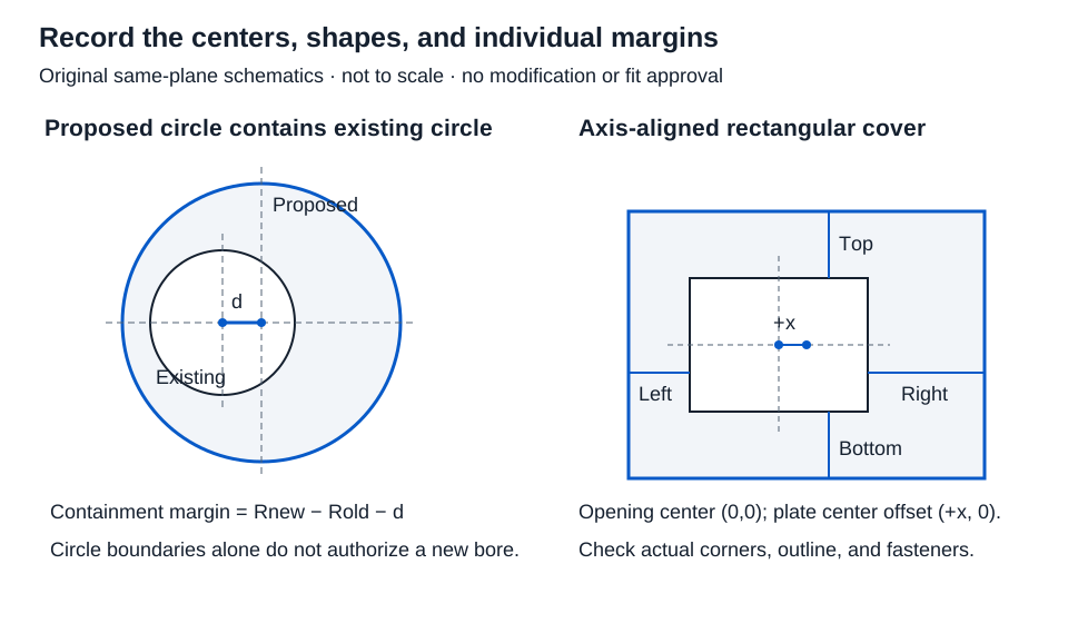
Before entering dimensions, identify the measurement plane, the outline of the actual opening, and the exact product drawing. Record center locations using the same reference. A visible face opening may differ from the recess, reinforcement, or usable mounting surface behind it.
| Question | Tool | Required geometry | Not established |
|---|---|---|---|
| Does one circular opening contain another? | Offset bore geometry | Two positive diameters and nonnegative straight-line center distance | Permission to enlarge the opening or fit of a lock body |
| Does a rectangular plate cover a rectangular opening? | Cover plate coverage | Opening and plate sizes, signed x/y offsets, nonnegative required margin | Screw support, rounded-corner coverage, or strength |
Calculate circular containment
Select a common length unit. Enter the existing diameter, proposed diameter, and straight-line distance between their centers. If offsets are measured separately, the center distance is √(Δx² + Δy²); it is not their sum.
Let R be the proposed radius, r the existing radius, and d the center distance:
Minimum radial containment margin = R − r − d
A positive margin means the proposed ideal circle contains the entire existing circle. Zero means boundary contact, which counts as containment in this model. A negative value means some part of the existing circle lies outside it. Circle overlap alone is not complete containment.
Worked example: an offset circular opening
Inputs: existing diameter 1 in, proposed diameter 2 in, center distance 0.25 in.
r = 1/2 = 0.5 in; R = 2/2 = 1 in
Margin = 1 − 0.5 − 0.25 = 0.25 in
Result: 0.250 in = 6.350 mm minimum radial margin; the new circle contains the old one geometrically. With the same diameters and 0.50 in center distance, the margin becomes 0.000 in at internal tangency. At 0.60 in, it is −0.100 in, so full containment fails. These values describe outlines, not a recommended reboring operation.
Calculate every rectangular edge margin
Use the opening center as (0,0). Positive x places the plate center to the right; positive y places it above the opening center. Keep plate and opening edges parallel. Enter positive widths and heights, signed offsets, and your separately supplied required margin.
Let opening width and height be W, H, plate width and height be P, Q, and plate-center offsets be x, y:
Left margin = (P − W)/2 − x
Right margin = (P − W)/2 + x
Bottom margin = (Q − H)/2 − y
Top margin = (Q − H)/2 + y
Moving the plate right reduces the left margin and increases the right margin. A negative margin means that opening edge extends beyond the plate.
Worked example: compare four margins
Inputs: opening 2 × 3 in; plate 4 × 5 in; plate-center offset (+0.25, 0) in; required margin 0.50 in on each edge. The required margin is a hypothetical supplied target.
The centered horizontal and vertical excesses are both 1 in per side. Applying the offsets gives:
| Edge | Calculation (in) | Margin (in) | Margin (mm) | Meets 0.50 in? |
|---|---|---|---|---|
| Left | 1 − 0.25 | 0.750 | 19.050 | Yes |
| Right | 1 + 0.25 | 1.250 | 31.750 | Yes |
| Bottom | 1 − 0 | 1.000 | 25.400 | Yes |
| Top | 1 + 0 | 1.000 | 25.400 | Yes |
Result: all four margins meet the supplied target. If x increases to 0.60 in, the left margin falls to 0.400 in and the target is no longer met, even though the rectangular opening remains geometrically covered. The tool includes the boundary when comparing a margin with its target.
Conclusion
Choose the model from the actual shape, retain the center references, and check the least favorable margin. Then review the real outline, fasteners, remaining material, recesses, and product instructions. Both tools retain exact dimensional arithmetic before three-decimal display, using 1 in = exactly 25.4 mm. Rounded display values create no installation allowance. The circle and edge-coordinate formulas are elementary geometry; they are not manufacturer compatibility rules.