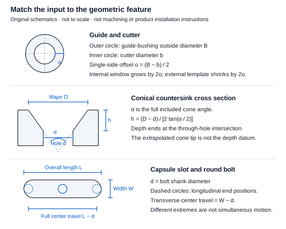
The correct machining input depends on the feature being modeled. A guide-bushing outside diameter controls a template offset. A countersink’s full included angle controls cone depth. A bolt’s shank diameter controls movement inside a slot. These dimensions cannot be substituted for one another, even when they appear on the same hardware drawing.
Establish that the operation is permitted by the applicable door, hardware, and tool instructions before using a calculated dimension as part of a work plan. The tools below calculate stated geometry or motion; they do not authorize modifications or select machining parameters.
Match the measurement to its physical feature
| Task | Required inputs | Output to interpret |
|---|---|---|
| Router template offset | Guide outside diameter, cutter diameter, finished width/height, internal or external mode | Single-edge offset and template envelope |
| Countersink or ideal drill point | Relevant diameters, full included angle, and mode-specific depth | Ideal axial cone depth |
| Slot travel | Overall slot length, slot width, shank diameter | Full one-axis bolt-center travel |
| Tap drill | Cutting/forming process, thread family, basic diameter, pitch/TPI, specified thread percentage | Formula hole diameter, not a selected drill |
| Drilling speed and feed | Diameter, supplied surface speed, feed per revolution, feed travel | Theoretical rpm, axial feed, and ideal feed time |
| Thread lead and travel | Axial pitch or TPI, start count, revolutions | Ideal lead and travel magnitude |
Calculate the bushing offset at each edge
For a hypothetical 5/8 in guide outside diameter and 3/8 in cutter, select inches and enter the two diameters in router template offset. Enter a finished envelope 1 × 2 1/4 in, then choose the template mode.
Single-edge offset o = (guide OD − cutter diameter)/2
o = (0.625 − 0.375)/2 = 0.125 in = 3.175 mm
An internal window must add that offset at both opposing edges. An external template must subtract it twice:
| Mode | Width calculation (in) | Height calculation (in) | Template envelope (in) |
|---|---|---|---|
| Internal window | 1 + 2 × 0.125 | 2.25 + 2 × 0.125 | 1.250 × 2.500 |
| External template | 1 − 2 × 0.125 | 2.25 − 2 × 0.125 | 0.750 × 2.000 |
The guide outside diameter must exceed the cutter diameter, and the finished and resulting template dimensions must remain positive. Guide outside diameter does not establish the internal clearance through which the cutter passes. The Lee Valley explanation supports this radius-difference relationship. Actual corner profiles, concentricity, guide depth, and tool clearance need separate checks.
Use the full included countersink angle
Select countersink mode and inches. For a hypothetical 0.5 in mouth, 0.25 in through hole, and 90° full included angle, enter those three values.
Depth h = (mouth diameter − hole diameter)/[2 tan(full angle/2)]
h = (0.5 − 0.25)/[2 tan 45°] = 0.125 in = 3.175 mm
The radius changes by 0.125 in, and the half-angle is 45°. Entering 45° as the full angle would describe a different cone. The mouth must exceed the positive through-hole diameter; the full angle must be greater than 0° and less than 180°.
Ideal drill-point mode instead models the cone down to its tip. For 0.5 in diameter, 90° included angle, and 1 in full-diameter depth, point height is 0.5/[2 tan 45°] = 0.25 in; ideal tip depth is 1 + 0.25 = 1.250 in. A real drill point may not be an exact cone. Neither mode establishes screw seating, remaining material, or a permitted breakthrough.
Distinguish full slot travel from movement each way
In slot travel, enter hypothetical overall length 1 in, width 3/8 in, and shank diameter 1/4 in:
Longitudinal center travel = overall length − shank diameter = 1 − 0.25 = 0.750 in
Transverse center travel = width − shank diameter = 0.375 − 0.25 = 0.125 in
From a centered position, the one-axis movement to an extreme is 0.375 in longitudinally or 0.0625 in transversely. These separate extremes are not available simultaneously near a curved slot end. The slot must be at least as long as it is wide, and the shank must not exceed its width. Washer size, clamping, and bearing remain outside the model.
Keep cutting parameters separate from geometric dimensions
For drilling speed and feed, obtain suitable surface speed and axial feed per revolution from the actual tooling data. A hypothetical 0.5 in drill, 100 SFM, 0.005 in/rev, and 1 in feed travel give:
rpm = 12 × 100/(π × 0.5) = 763.943726…
Feed = rpm × 0.005 = 3.819718… in/min
Ideal time = 1/feed × 60 = 15.707963… s
The displays are 763.944 rpm, 3.820 in/min, and 15.708 s. They use unrounded intermediate values. Diameter, speed, and feed must be positive; travel can explicitly be zero. The time excludes setup, pecking, approach, and retraction.
A tapped hole uses different inputs. Select cutting or forming and UNC/UNF or M/MF before applying the cited Guhring formulas, printed page 240. Use basic major diameter, not a screw-number label. The specified thread percentage is a formula input, not joint strength or an automatically acceptable hole tolerance.
For a hypothetical cutting tap in the UNC/UNF family, enter 0.25 in basic major diameter, 20 TPI, and 75% desired thread. The cited inch cutting formula gives hole = 0.25 − 0.01299 × 75/20 = 0.2012875 in, or exactly 5.1127025 mm. The displays are 0.201 in / 5.113 mm. This does not select a drill size or an acceptable hole range. Forming and metric formulas use different coefficients; changing the process or thread family changes the calculation.
For ideal threaded travel, a single-start 20 TPI thread has pitch and lead 1/20 = 0.05 in/rev. At 0.25 revolution, travel is 0.0125 in = 0.3175 mm, displayed 0.013 in / 0.318 mm. Multiple starts multiply lead; backlash and permitted adjustment remain separate.
Retain the drawing and the unrounded values
Length conversion uses exactly 25.4 mm per inch. Geometry displays use three decimals, with exact ties rounded away from zero; trigonometric results are approximations. These display rules do not supply machining tolerances. Keep the actual component and tool identities, references, original dimensions, chosen model, and results on the machining-input record. Use the applicable instructions to decide how those results can be used.