A load schedule becomes a charge calculation only when its currents share one electrical boundary and its time intervals do not overlap. Decide whether the task is a changing timeline, an ideal constant-current duration, a nominal battery arrangement, or a brief capacitor voltage decline. These models use related quantities, but they do not make interchangeable predictions of real backup performance.
Put the whole system on one timeline
In the DC timeline charge calculator, each row is one consecutive phase: duration in decimal hours, whole-system current in A, and voltage in V. When devices run simultaneously, combine their currents for that interval before entering a row. Do not list overlapping device operating hours as separate chronological phases.
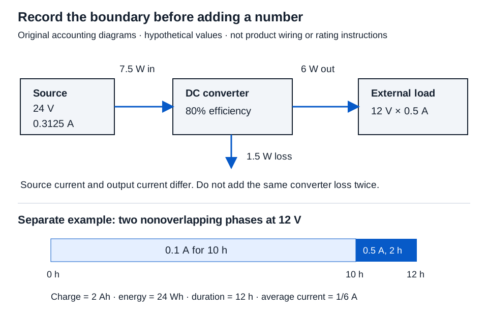
Current must be defined on the same side of a converter in every phase. Translate output-side operating points to the battery or source boundary first, using actual voltage and efficiency with the converter calculator. A source’s alternative maximum-load scenarios do not automatically describe a daily schedule.
Calculate charge, energy, and average current separately
For 10 h at 0.1 A and 12 V, followed by 2 h at 0.5 A and 12 V, enter:
10,0.1,12
2,0.5,12
The independent calculations are:
| Phase | Duration (h) | Whole-system current (A) | Voltage (V) | Charge I × t (Ah) | Energy V × I × t (Wh) |
|---|---|---|---|---|---|
| First | 10 | 0.1 | 12 | 1 | 12 |
| Second | 2 | 0.5 | 12 | 1 | 12 |
| Total | 12 | 2.000 | 24.000 |
Average current = total charge / total time = 2/12 = 1/6 A ≈ 0.167 A
Ah measures charge; Wh measures energy. The two phases have equal charge and energy here because each removes 1 Ah at the same voltage. A different voltage would change energy without changing that phase’s Ah. These relationships follow current as charge per time and power as VI.
Enter an explicit off phase when it is part of the timeline. Adding 2 h at 0 A and 12 V changes duration to 14 h and average current to 2/14 ≈ 0.143 A; charge remains 2 Ah and energy 24 Wh. Omitting those hours would produce a different average.
The tool supports 1–30 phases, nonnegative values, and a positive combined duration. Use decimal hours, not clock notation. A blank field is not zero. Results use unrounded totals before three-decimal half-up display rounding.
Use an ideal constant-current baseline for its stated question
The ideal battery charge calculator offers two modes:
| Mode | Inputs | Formula | Hypothetical result |
|---|---|---|---|
| Ideal runtime | Positive capacity and positive battery-side current | t = Q/I | 7 Ah / 0.5 A = 14.000 h |
| Ideal capacity | Nonnegative current and duration | Q = It | 0.5 A × 14 h = 7.000 Ah |
Select the desired mode and enter the values in Ah, A, and hours. This ideal calculation does not determine usable charge from a battery label. Real runtime depends on discharge rate, temperature, cutoff, aging, and equipment behavior. Do not treat a maximum-current scenario as a timeline without establishing how long that state lasts.
Describe nominal battery arrangement without claiming usable runtime
The identical battery bank calculator assumes equal strings of identical nominal units. Enter 12 V, 7 Ah, two units in series, and three parallel strings:
Units = 2 × 3 = 6
Nominal voltage = 12 × 2 = 24.000 V
Nominal capacity = 7 × 3 = 21.000 Ah
Nominal energy = 24 × 21 = 504.000 Wh
Series count multiplies voltage; it does not multiply Ah. Parallel string count multiplies Ah. Ratings must be positive, and counts must be whole numbers 1–1000. These are nominal arithmetic results, not wiring or charging instructions. Compatibility, balancing, protection, permitted connections, and discharge behavior remain outside the model.
Keep a capacitor hold separate from battery charge
The ideal capacitor hold calculator models a capacitor directly supplying constant current while its voltage decreases. Enter 0.1 A, 0.1 s, and 1 V allowed capacitor drop:
Removed charge = It = 0.1 × 0.1 = 0.01 coulomb
C = It/ΔV = 0.01/1 = 0.01 F = 10000.000 µF
The charge-voltage relationship supports this ideal baseline. Current and time may explicitly be zero; the allowed voltage drop must be positive.
Capacitor-node voltage drop is not automatically a device-terminal allowance. ESR, leakage, tolerance, initial voltage, converter behavior, and actual load variation require further information. This calculation does not choose a capacitor rating or guarantee hold-up time.
Preserve the schedule and distinguish nominal from usable values
Record phase boundaries, rail, current-data source, efficiencies, original values, and results on the DC boundary and time record. Keep full precision until final display; a rounded average such as 0.167 A is not the exact 1/6 A used in the timeline.
Use actual discharge curves, operating conditions, and device requirements for a real backup assessment. The completed arithmetic describes the stated timeline or ideal model. It does not establish service runtime, battery suitability, or standby compliance.