A door’s motion can be represented as a point, a thick rectangle, a projected width, a sliding interval, or a folding linkage. Each representation answers a different question. This atlas identifies the origins, axes, and physical dimensions required by the supported calculators, with numerical checks that show why one model’s result cannot be substituted for another’s.
Match the actual mechanism to the diagram
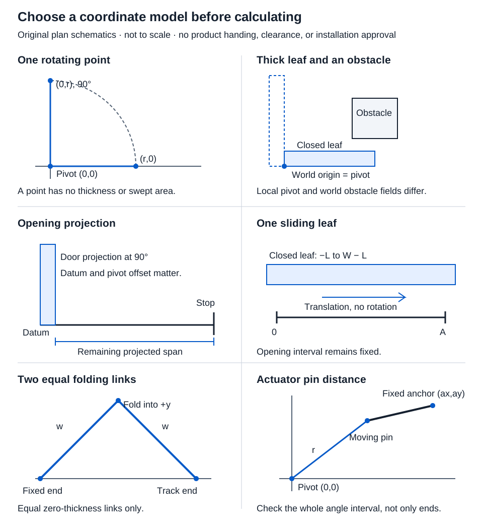
| Tool | Required reference | Result and main boundary |
|---|---|---|
| Point swing | Pivot (0,0), point starts at (r,0) | Position, chord, and arc; no leaf thickness |
| Thick-door sweep | Local pivot in closed leaf; obstacle coordinates relative to pivot | Plan-rectangle contact/intersection intervals; no height or hardware projections |
| Opening projection | Hinge-side opening datum, axis offset, pivot within closed leaf | Door projection and remaining span to opposite stop; no full compliance check |
| Sliding travel | Opening interval x = 0 to A and stated outer overlaps | Uncovered span after translation; no track or pocket design |
| Equal-panel bifold | Fixed end at origin, far end on +x track, fold into +y | Endpoint retraction and joint depth for two equal zero-thickness links |
| Actuator stroke | Pivot at origin, moving pin starts at (r,0), fixed anchor in same plane | Pin-to-pin length range across the whole angle interval; no actuator force or body clearance |
Choose the model before collecting numbers. Mark the physical origin, positive axes, observation plane, and unit on the layout. In particular, a local pivot coordinate inside the closed leaf is not an obstacle’s world coordinate measured from the pivot.
Worked example: point displacement and arc travel
In the point swing tool, enter 36 in radius and 90° angle. The point starts at (36,0) in. For angle θ in radians:
x = r cos θ; y = r sin θ
Chord = 2r sin(θ/2); arc = rθ
At θ = π/2, the final point is (0.000, 36.000) in. The chord is 36√2 ≈ 50.9116882 in, displayed as 50.912 in. The arc is 18π ≈ 56.5486678 in, displayed as 56.549 in. The chord is straight-line displacement between positions; the arc follows the circular path. Neither is an opening width.
Include leaf thickness for a projection question
The projection tool supports 0–90° and a pivot within the closed leaf’s width and thickness. It uses the complete rectangular leaf’s rightmost x extent relative to the opening datum. Enter positive opening width, leaf width and thickness, and nonnegative pivot coordinates and axis offset.
Example inputs: opening 36 in, leaf 36 in, thickness 1.75 in, local pivot (0,1.75) in, axis offset 0 in, angle 90°.
Projection = axis offset + (width − pivot x) cos θ + pivot y sin θ
Projection = 0 + 36 × 0 + 1.75 × 1 = 1.750 in
Remaining span = max(0, 36 − 1.75) = 34.250 in
At 0° the projection is 36 in and the remaining span is zero. The Access Board’s door guide describes a stop-to-door-face clear-width measurement at 90°. This calculated projection does not check the actual stop, hardware projections, maneuvering space, or all other required conditions.
For obstacle contact over a swing, use the sweep tool instead. Enter the closed-leaf dimensions and pivot, then the obstacle’s left, right, bottom, and top plan coordinates relative to the pivot. Contact counts as intersection within the tool’s numerical comparison allowance. The returned intervals assess the entered rectangles, not handles, closers, floor clearance, or objects at another height.
Worked examples: sliding and folding
For one sliding leaf, the opening is [0,A] and the closed leaf is [−L, W−L], where L is left overlap. Select the direction and enter nonnegative travel.
Example inputs: opening 36 in, leaf 40 in, left overlap 2 in, rightward travel 20 in. The closed leaf spans [−2,38] in, so right overlap is 40 − 36 − 2 = 2 in. After travel it spans [18,58] in, leaving 18.000 in of the opening uncovered. Full rightward clearance requires 36 + 2 = 38.000 in travel. The pair mode instead moves two individually sized leaves apart; do not enter their combined width as one leaf.
For the bifold tool, enter two equal 18 in panels and angle 60°:
Track endpoint = 2 × 18 × cos 60° = 18.000 in
Fold depth = 18 × sin 60° = 9√3 ≈ 15.588 in
Retraction from flat = 36 − 18 = 18.000 in
The supported fold angle is 0–90°. Panel thickness, hinge offsets, overlap, and actual running gear are absent.
Check actuator lengths inside the interval
For moving radius r and fixed anchor (a,b), the pin distance is:
Length(θ) = √[(r cos θ − a)² + (r sin θ − b)²]
Example inputs: r 10 in, fixed anchor (0,10) in, final angle 180°, starting at 0°. Both endpoint lengths are √200 ≈ 14.142 in. At 90°, however, the moving pin reaches the fixed anchor and length is 0 in. The full geometric stroke is therefore 14.142 in, not zero.
The zero-length position makes this physical layout unusable despite the defined mathematics. Check articulation, body size, mounting limits, force, and collisions separately. Comparing only start and end lengths can miss an interior minimum or maximum.
Conclusion and basis
Keep coordinates and mechanism assumptions with each result. Use unrounded trigonometric values between steps and round final displays to three decimals. OpenStax’s rotational variables supports the angular relationships; the other models follow their stated rectangle, interval, linkage, and distance geometry. Exact unit conversions preserve the same physical inputs. A positive remaining span or a no-intersection result describes only the selected model.