A door mass estimate is useful input for a hinge assessment, but it does not supply hinge capacity, count, or fastener requirements. Mass distribution, pivot position, support assumptions, door construction, and the actual hinge geometry remain separate. This reference shows how to prepare those quantities without confusing mass, force, inertia, and open hinge width.
Establish what the mass includes
Prefer applicable measured or manufacturer-stated assembly mass. Record whether hardware, glazing, reinforcement, and finishes are included. The door weight calculator can use volume and supplied density for a uniform rectangular solid, or area and supplied mass per unit area for a rectangular panel. Neither mode infers a hollow or layered door’s construction from its outer dimensions.
Example inputs: width 36 in, height 80 in, thickness 1.75 in, hypothetical uniform density 40 lb/ft³.
Volume = 36 × 80 × 1.75 = 5,040 in³
Volume = 5,040/1,728 = 35/12 ft³
Mass = (35/12) × 40 = 350/3 lb ≈ 116.6666667 lb
Mass in kg = (350/3) × 0.45359237 ≈ 52.9191098 kg
Displayed results: 116.7 lb and 52.9 kg. All dimensions and density must be positive. The familiar label “door weight” reports mass in lb and kg; it does not report force in lbf or N. The entered density is an example, not a recommended material value.
For the area-based mode, retain the product and configuration, source document or page, revision or access date, original lb/ft² or kg/m² value, rectangular dimensions, and what the stated figure includes. A hypothetical 900 × 2000 mm panel with 30 kg/m² has 0.9 × 2 × 30 = 54 kg. This is a separate panel example, not the mass of the uniform solid above. Do not add a frame or hardware mass twice if the source already includes it.
Account for each component once
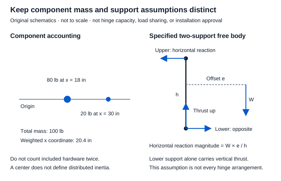
For center of mass, select one mass unit and one coordinate unit. Use a common origin and axes, and enter 1–50 rows as mass, x, y, z. Each mass must be positive; coordinates can be signed. Coordinates locate each component’s own center of mass, rather than its mounting edge.
| Component | Mass (lb) | Center x (in) | Center y (in) | Center z (in) |
|---|---|---|---|---|
| Door body, excluding the added component | 80 | 18 | 40 | 0 |
| Separate added component | 20 | 30 | 40 | 0 |
Total mass = 80 + 20 = 100 lb
Center x = (80 × 18 + 20 × 30)/100 = 20.4 in
Both components have the same y and z coordinates, so the combined center is (20.400, 40.000, 0.000) in. Do not add hardware a second time if its mass is already included in another row. These component values are separate from the uniform-solid example above.
Select the mechanical calculation deliberately
| Quantity | Inputs and meaning | What the result does not supply |
|---|---|---|
| Uniform-leaf inertia | Uniform mass, width/thickness, pivot location, angular speed in rad/s | Actual inertia of an arbitrary composite door or closing performance |
| Ideal support reactions | Weight as force, horizontal center offset, vertical support separation | Real multi-hinge load sharing or hinge rating |
| One-force torque | Applied force, radius, included force/radius angle | Net torque from all forces or opening-force compliance |
| Pressure moment | Uniform net pressure and rectangular area about the specified edge | A pressure recommendation or closer selection |
| Open hinge width | Thickness, specified hinge backset, required clearance | Catalog size, hinge capacity, or approved mounting |
Inertia concerns resistance to angular acceleration, not the static torque from gravity. For the supported uniform leaf, I = m[(w² + t²)/12 + (w/2 − px)² + (t/2 − py)²], with SI lengths for kg·m². A center-of-mass coordinate alone does not establish the uniform distribution this formula assumes.
Worked example: the specified two-support model
The ideal support tool assigns all vertical thrust to the lower support. Equal and opposite horizontal reactions at two supports balance the gravity moment. Enter weight as a positive force, a nonnegative horizontal offset, and positive vertical support separation.
Inputs: 100 lbf weight, 18 in offset, 60 in support separation.
Gravity moment = 100 × 18 = 1,800 lbf·in
Each opposing horizontal reaction = 1,800/60 = 30.000 lbf
The lower support carries 100.000 lbf upward; the upper carries no vertical thrust under this model. The horizontal reactions form a couple, so their directions oppose one another. Real hinges can share thrust and transmit loads differently. Do not divide the weight by an assumed hinge count and call that a verified hinge demand.
Worked example: conditional full-mortise hinge width
Hager’s Determine the Size of Hinge gives the geometric relationship used by the tool for its stated full-mortise application:
Open width = 2 × (door thickness − hinge backset) + required clearance
Confirm that the source’s configuration and reference face apply. Hinge backset here is not the lock’s door-edge-to-centerline backset. The tool requires positive thickness, nonnegative backset and clearance, and backset less than thickness.
Hypothetical inputs: thickness 1.75 in, hinge backset 0.25 in, clearance 1 in.
Open width = 2 × (1.75 − 0.25) + 1 = 4 in = 101.6 mm
Displayed result: 4.000 in / 101.600 mm, a conditional geometric minimum. It is not a selected hinge size or capacity rating.
Conclusion and sources
Retain the mass source, included components, coordinate references, and model assumptions with each result. The mass estimator displays one decimal place; the other worked dimensional and force results display three. Do not reuse rounded intermediates. Center-of-mass principles, static equilibrium, and exact unit definitions support the calculations. Submit the actual assembly, hardware, reinforcement, fastener, and service-condition information for the applicable manufacturer assessment; none of these tools selects a hinge.