A wire-resistance number is useful only when its path and length basis are clear. The two-wire voltage drop calculator needs resistance per unit length of one conductor and the one-way source-to-load distance. The branch-network calculator needs complete outgoing-and-return resistance for each segment. Entering one kind of number in the other field can count the return twice or omit it entirely.
Follow the current out and back
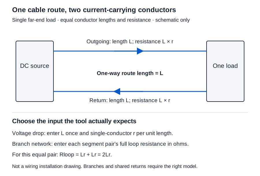
For equal conductors, each conductor contributes Lr and the loop contributes 2Lr, provided L and r use matching length units. If r is stated in Ω/1,000 ft, divide the one-way feet by 1,000 first. If r is in Ω/km, use kilometers. The voltage-drop tool converts the selected bases independently.
| Available information | Required qualification | Where it belongs |
|---|---|---|
| Single-conductor resistance per length | Ω/1,000 ft or Ω/km; actual conductor and temperature | Two-wire voltage drop resistance field |
| Source-to-load route length | ft or m, one way | Two-wire one-way distance field, entered once |
| Complete outgoing/return resistance for one segment | Ω for that full pair; included connections identified | DC branch network segment loop resistance |
| Resistance of one conductor over a known route | Ω, conductor length and temperature | Add the actual return contribution before treating it as a segment loop |
| AWG designation or length alone | No applicable resistance value | Insufficient to fill either resistance field |
Keep the datasheet identity, revision, material, temperature, and typical-versus-maximum qualification beside the resistance figure. Do not transfer a number to a different cable construction simply because the AWG designation matches.
Worked example: one circuit represented two ways
Hypothetical inputs: 24 V source, 1 A stated far-end current, 100 ft one-way route, and 10 Ω/1,000 ft per conductor. These are arithmetic inputs, not cable specifications.
One conductor = (100/1,000) × 10 = 1 Ω
Loop resistance = 1 + 1 = 2 Ω
Voltage drop = current × loop resistance = 1 × 2 = 2 V
Load-end voltage = 24 − 2 = 22 V
Wire power loss = current² × loop resistance = 1² × 2 = 2 W
In two-wire voltage drop, select voltage-drop mode and enter source 24, current 1, distance 100 ft, and resistance 10 Ω/1,000 ft. Do not double the distance. The tool already includes the equal return.
In DC branch network, enter source 24 and one node row 0, 2, 1: source parent 0, full segment loop resistance 2 Ω, local load 1 A. That representation already contains the return and requires no further factor of two.
| Representation | Entered length or loop resistance | Loop resistance | Load-end voltage |
|---|---|---|---|
| Correct two-wire input | 100 ft, 10 Ω/1,000 ft | 2.000 Ω | 22.000 V |
| Correct one-node network | Complete segment 2 Ω | 2.000 Ω | 22.000 V |
| Return counted twice in two-wire input | 200 ft, 10 Ω/1,000 ft | 4.000 Ω | 20.000 V |
| Complete segment doubled again | Complete segment entered as 4 Ω | 4.000 Ω | 20.000 V |
The correct drop percentage is 2/24 × 100 = 25/3%, displayed as 8.333%. No intermediate value is rounded. The other displayed results are 2.000 Ω, 2.000 V drop, 22.000 V load end, and 2.000 W conductor loss.
Change units without changing the path
The same 100 ft route is exactly 30.48 m. Entering 30.48 m while retaining 10 Ω/1,000 ft gives the same result. If you also change the resistance basis, convert its number: 10 Ω/1,000 ft = 32.80839895… Ω/km. Selecting Ω/km but leaving the value at 10 describes a different conductor resistance.
Both selectors interpret the typed number in the selected unit; they do not automatically rewrite that number. Retain sufficient precision in any converted data and preserve the original source value.
Solve a stated length boundary separately
In maximum-length mode, the same tool rearranges the two-wire model:
Maximum one-way length = (source voltage − stated minimum)/(2 × current × resistance per length)
With 24 V, a supplied 22 V minimum, 1 A, and 0.01 Ω/ft per conductor, the length is (24 − 22)/(2 × 1 × 0.01) = 100 ft = 30.48 m, displayed as 100.000 ft / 30.480 m. Source, minimum, current, and resistance must be positive; the minimum cannot exceed the source. A minimum equal to the source gives zero length under this model.
This is a theoretical voltage boundary, not a recommended cut length. The forward mode permits zero current or zero route length, but still requires positive source voltage and conductor resistance per length.
Know when another model is needed
For applicable bulk resistivity and conductive area, the wire resistance tool uses R = ρL/A. It can report one conductor or an equal loop and can apply a supplied linear temperature coefficient. Keep resistivity units, reference temperature, and valid range with the input. Its per-conductor result and complete-loop result serve different downstream fields.
The branch-network tool accepts 1–30 nodes, with each parent referring to the source or an earlier node. Every segment carries its own local current plus all downstream load currents. Its specified tree uses independent outgoing/return pairs; shared returns, rings, multiple supplies, and voltage-dependent loads are outside the model.
A zero or negative calculated load-end voltage means the stated constant-current operating point is unusable there. It does not mean a passive wire creates reverse polarity. A positive voltage alone also does not prove the actual device will operate.
Conclusion and sources
Name the resistance path first, then enter the distance and current using the selected model’s definitions. Keep exact values until the final three-decimal display, and check actual device voltage requirements separately. OpenStax’s series-resistance treatment supports adding the two conductor resistances; Ohm’s law supports IR drop. Exact unit definitions supply the foot-to-meter relationship. None of these tools provides ampacity rules or a product compatibility decision.