A template needs the right identity as well as the right dimensions. First confirm that it applies to the exact hardware, door construction, and installation. Then check its printed scale or coordinate transformation. A perfectly scaled copy of the wrong revision is still the wrong template.
This guide separates four operations: correcting uniform print scale, moving an existing coordinate pattern, generating a genuinely equal straight spacing, and generating equal centers on a circle. None of them reconstructs missing manufacturer’s hole locations.
Confirm the source and measurement references
Record the manufacturer, model or series, document revision, page, viewing side, and applicable installation conditions on the template verification sheet. Identify the drawing’s origin, positive axes, centerlines, and door-edge references. A hinge backset, a lock backset, and a distance from a trim edge are not interchangeable datums.
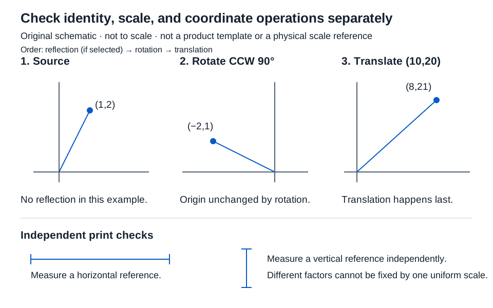
For a printed template, retain the paper size, printer setting, and any fit-to-page option. Measure stated horizontal and vertical references independently. A horizontal check cannot reveal a separate vertical scaling error.
| Condition | Appropriate calculation | Information that must already be known |
|---|---|---|
| Both print axes have the same proportional size error | Print scale calibration | Stated reference, measured print, actual current percentage |
| A documented pattern changes origin or orientation | Template coordinates | Original points, reflection, rotation, translation |
| Centers intentionally share one straight equal spacing | Equal hole spacing | Span, end-center offsets, center count, start reference |
| Centers intentionally share one full-circle pattern | Bolt circle layout | Pitch circle diameter, center, first angle, count, direction |
Correct uniform print scale by a ratio
Assume a hypothetical 10 in reference measures 9.8 in when printed at 100%.
- In print scale calibration, enter stated length
10, measured length9.8, and inches. - Enter
100as the percentage actually used. - Calculate the correction, then make another print using the proposed setting.
- Measure fresh horizontal and vertical references. Do not accept the calculation in place of that physical check.
The governing relationship and result are:
Next percentage = current percentage × stated length ÷ measured length
100 × 10 ÷ 9.8 = 5000/49% ≈ 102.041%
The measured print error is (9.8/10 − 1) × 100 = −2%, but adding exactly two percentage points would give 9.8 × 1.02 = 9.996 in. Correction is a ratio, so it is not simply the negative of the observed percentage error.
Lengths and current percentage must be positive. The tool reports three-decimal results. It assumes uniform proportional scaling and unchanged printer behavior. If the axes need different factors, or local distortion remains, a single percentage cannot correct the drawing.
Verify the coordinate order with known points
The coordinate tool reflects selected original coordinates first, rotates counterclockwise second, and translates last. Choose one length unit, then enter one original x,y point per line. Enter signed translation distances in that same unit and a signed rotation in degrees. A reflection is a geometric operation; it does not establish a manufacturer’s handing designation.
For P = (1,2) in, no reflection, +90° rotation, and translation (10,20) in:
x′ = x cos θ − y sin θ = 1 × 0 − 2 × 1 = −2
y′ = x sin θ + y cos θ = 1 × 1 + 2 × 0 = 1
Final point = (−2 + 10, 1 + 20) = (8.000,21.000) in
Check a second point. For Q = (3,2) in, the same operations give (8.000,23.000) in. Their original 2 in horizontal separation becomes 2 in vertical separation. That second check helps reveal an incorrect orientation even when one point happens to match. The rotation convention is mathematical, not a product-specific viewing convention.
Check center positions before marking a pattern
For a hypothetical straight 80 in span with 10 in end offsets and four centers:
Spacing = (80 − 10 − 10)/(4 − 1) = 20 in
The tool requires 2–100 centers, a positive span, and end offsets totaling less than that span. Offsets may explicitly be zero. There are three intervals between four centers.
| Center | From start datum (in) | From start datum (mm), exact |
|---|---|---|
| 1 | 10 | 254 |
| 2 | 30 | 762 |
| 3 | 50 | 1270 |
| 4 | 70 | 1778 |
For a separate full-circle example, enter a 4 in pitch circle diameter, center (0,0), four holes, first angle 0°, and counterclockwise numbering. Angular spacing is 360/4 = 90°; coordinates are (2,0), (0,2), (−2,0), (0,−2) in. The circle diameter passes through the hole centers; it is not a hole diameter or the outside trim diameter.
Finish with independent drawing checks
Use the original drawing values through the calculation; round only the final display. Exact length conversion uses 25.4 mm per inch. Retain the original pattern, operation order, print settings, and measured checks together. Before marking or machining, reconcile control dimensions, viewing side, and applicable product instructions. When a reference or pattern is missing, obtain the correct template rather than inventing geometry.