Before calculating an EOL resistance, LED resistor, RC delay, or RL decay, match the actual circuit connections and initial conditions to the supported model. A product label alone does not establish that match. A “DEOL” input can use a different resistor arrangement, and a lock’s suppression circuit can behave very differently from source-free RL decay.
This atlas shows the exact ideal arrangements used by the calculators. The diagrams and numerical examples are explanatory models, not instructions to change controller wiring or lock electronics.
Compare the complete topology
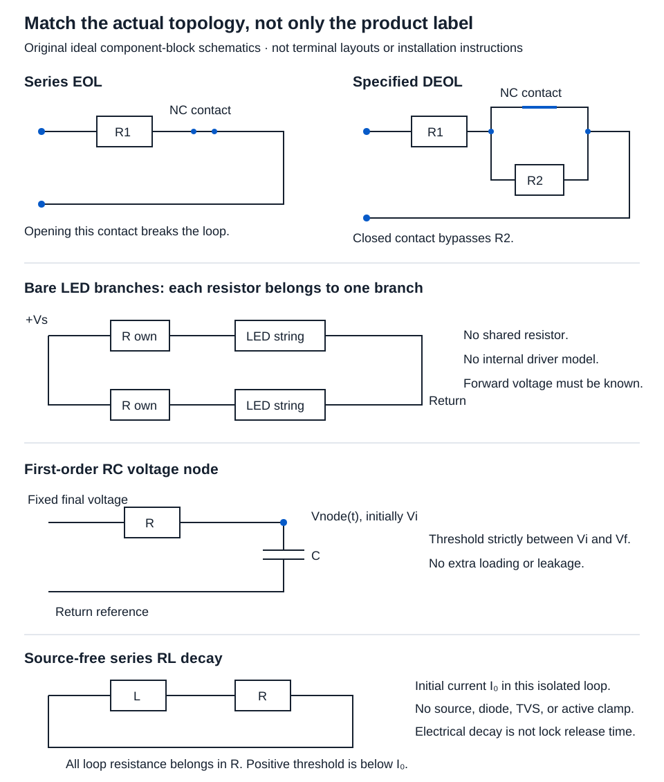
Trace the nodes and branches on the actual schematic. Identify every source, resistor, contact, capacitor, inductor, diode, clamp, and connected load that affects the question. Obtain component values and the applicable operating conditions. If a significant branch or clamp differs from the model, a result from the simplified circuit does not resolve the actual circuit.
Worked example: EOL and DEOL states
In EOL / DEOL resistance, select the topology and enter positive resistor values in ohms. For a 1 kΩ resistor, enter 1000, rather than 1.
The modeled alarm contact is normally closed. EOL places R1 in series with the contact. DEOL places R1 in series with the parallel combination of the contact and R2. With the contact closed, its ideal zero resistance bypasses R2. Opening it leaves R1 and R2 in series.
Hypothetical inputs: R1 1,000 Ω, R2 2,000 Ω for DEOL.
DEOL normal = R1 + 0 = 1,000 Ω
DEOL alarm = R1 + R2 = 1,000 + 2,000 = 3,000 Ω
| Physical state | EOL result | DEOL result |
|---|---|---|
| Alarm contact closed | 1,000.000 Ω | 1,000.000 Ω |
| Alarm contact open | Open circuit | 3,000.000 Ω |
| Series wire or modeled series tamper open | Open circuit | Open circuit |
| Ideal short directly across panel terminals | 0 Ω | 0 Ω |
Open circuit is a state, not a fabricated large resistance. Other short locations can bypass different components. Cable resistance, contact resistance, controller thresholds, and recognized alarm states require actual product documentation; none is inferred from this table.
Worked example: a resistor for each LED branch
The LED series resistor calculator models identical strings of bare LEDs, with one separate resistor per branch. Enter positive source voltage, stated forward voltage per LED, target current in mA per branch, series LED count, and branch count. Counts are whole numbers 1–1,000. Source voltage must exceed the total stated LED forward drop.
Inputs: source 12 V, forward drop 2 V, one LED per branch, 10 mA target current, two branches.
Branch current = 10/1,000 = 0.01 A
Resistor drop = 12 − 1 × 2 = 10 V
Theoretical resistor = 10/0.01 = 1,000 Ω per branch
Each resistor's dissipation = 10 × 0.01 = 0.100 W
Total current = 2 × 0.01 = 0.020 A
These outputs do not choose a preferred resistance or wattage rating. Actual forward-voltage variation, supply limits, tolerances, and thermal conditions still matter. A complete rated indicator with an internal driver is not this bare-LED model.
Worked example: first-order RC threshold time
The RC threshold calculator takes resistance in Ω, capacitance in µF, initial voltage, final asymptotic voltage, and threshold. R and C must be positive. Supported voltages are nonnegative, the initial and final values must differ, and the threshold must lie strictly between them.
V(t) = V_final + (V_initial − V_final)e^(−t/RC)
Threshold time = −RC ln[(V_threshold − V_final)/(V_initial − V_final)]
Inputs: R 1,000 Ω, C 1,000 µF = 0.001 F, initial 0 V, final 10 V, threshold 5 V.
RC = 1,000 × 0.001 = 1 s
t = −1 × ln[(5 − 10)/(0 − 10)] = ln 2 ≈ 0.693147 s
Displayed results: time constant 1.000 s, crossing time 0.693 s. They are different quantities. A threshold at the final 10 V has no finite crossing time in this ideal model and is rejected. Extra loads, leakage, hysteresis, and firmware timing are absent.
Worked example: source-free RL decay
The ideal RL decay calculator assumes an isolated inductor discharging through a positive total series resistance, with no remaining source, diode clamp, TVS, or active suppression model. Enter positive inductance in H, resistance in Ω, initial current in A, and a positive threshold below the initial current.
Current(t) = I_initial e^(−tR/L)
Time constant = L/R; threshold time = (L/R) ln(I_initial/I_threshold)
Inputs: L 1 H, R 10 Ω, initial current 1 A, threshold 0.5 A.
Initial stored energy = LI²/2 = 1 × 1²/2 = 0.500 J
Time constant = 1/10 = 0.100 s
t = 0.1 × ln(1/0.5) ≈ 0.0693147 s, displayed as 0.069 s.
Zero current is approached asymptotically; it is not a supported finite threshold. An electrical threshold is not automatically a lock’s mechanical release threshold. Do not use this result to choose suppression components or predict product release timing.
Conclusion and sources
Use the tool only after the actual topology, units, and initial conditions match. Keep intermediate logarithmic values unrounded and use final three-decimal displays. OpenStax’s series and parallel resistance, RC circuits, and RL circuits support the ideal relationships. Product state recognition, ratings, wiring, and installation requirements remain separate evidence.