A door size calculation is useful only when its opening, plane, and gaps are defined. A nominal frame size does not identify the clear opening at the leaf, and one floor reading cannot describe every point the door passes over. Start with a survey that separates opening geometry, leaf deductions, and floor elevations.
Establish the plane and the endpoints
Identify the edges of the opening at the plane occupied by the leaf. Record stops, rabbets, thresholds, and the applicable drawing reference on the door and frame survey sheet. Keep measured dimensions separate from required gaps. Do not use an outside frame dimension or rough opening as a clear leaf opening.
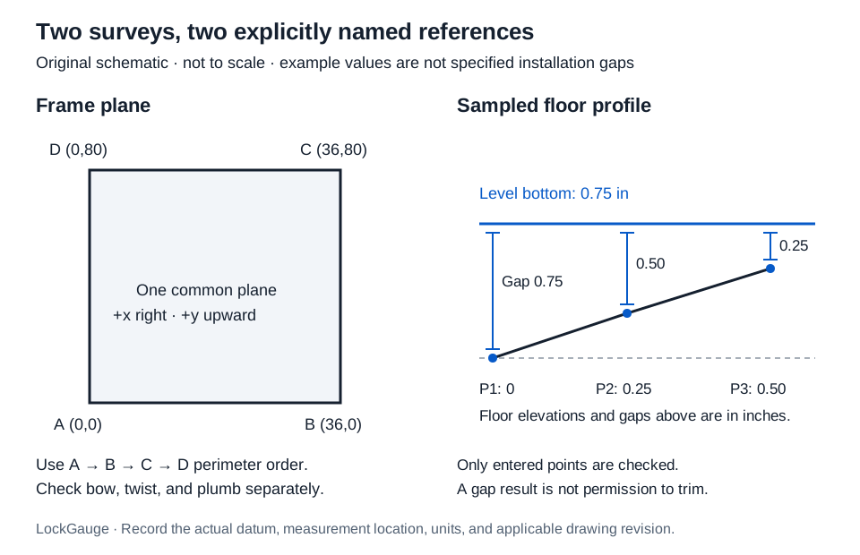
If the frame may be out of square, measure four corners in one plane and enter them in perimeter order in the frame geometry calculator. Use one origin and axis convention throughout. The tool derives side lengths, diagonals, and corner angles. Equal diagonals alone do not prove a rectangle: an isosceles trapezoid can also have equal diagonals. Four corners cannot establish straight edges, plumb, or absence of twist outside that plane.
| Information available | Calculation | What remains outside it |
|---|---|---|
| Four ordered planar corners | Frame geometry | Bow, out-of-plane twist, plumb, and a usable rectangular leaf size |
| Clear rectangular opening and supplied gaps | Door leaf dimensions | Product-specific gap requirements and rough-opening conversion |
| Level bottom and surveyed floor elevations | Bottom gap profile | Unmeasured high spots, sag, seals, and permitted trimming |
| Parallel faces and one straight beveled edge | Door edge bevel | Handing and the manufacturer’s lock measurement reference |
| Two dimensions with justified thermal data | Door and frame thermal expansion | Installed restraint, moisture effects, and actual gap prediction |
Calculate a leaf from explicit gaps
For a hypothetical rectangular opening 36 in wide × 80 in high, assume the separately supplied gaps are 1/8 in at each side, 1/8 in at the top, and 3/4 in at the bottom. These values demonstrate arithmetic; they do not prescribe an installation.
- Select one-leaf mode and inches.
- Enter opening width
36and height80. - Enter left, right, and top gaps as
1/8, and bottom gap as3/4. - Calculate and reconcile the result with the complete dimension chain.
Leaf width = opening width − left gap − right gap
36 − 0.125 − 0.125 = 35.750 in = 908.050 mm
Leaf height = opening height − top gap − bottom gap
80 − 0.125 − 0.75 = 79.125 in = 2009.775 mm
For two equal leaves, select pair mode and also supply the meeting gap. With a 72 in opening, the same side gaps, and 1/4 in meeting gap:
Each width = (72 − 0.125 − 0.125 − 0.25)/2 = 35.750 in
Check the full width: 35.75 + 35.75 + 0.125 + 0.125 + 0.25 = 72 in. The meeting gap is counted once between the leaves. Unequal leaves and overlapping astragals require a different geometry.
The tool accepts an explicit zero gap but does not fill missing gaps with zero. The opening must exceed the deductions so both resulting dimensions remain positive. Exact values are calculated before three-decimal half-up display rounding.
Evaluate the floor at the points actually surveyed
In bottom gap profile, use the same vertical datum for bottom elevation and all floor readings. Enter bottom elevation 0.75 in, floor elevations 0, 0.25, 0.5 in, and a hypothetical required minimum 0.5 in. Enter one floor elevation per line, retaining each point’s location separately.
Gap at each point = bottom elevation − floor elevation
| Survey point | Floor elevation (in) | Calculation (in) | Gap (in) |
|---|---|---|---|
| P1 | 0 | 0.75 − 0 | 0.750 |
| P2 | 0.25 | 0.75 − 0.25 | 0.500 |
| P3 | 0.50 | 0.75 − 0.50 | 0.250 |
The smallest entered gap is 0.250 in. The geometric elevation increase is max(0, 0.5 − 0.25) = 0.250 in. If the supplied minimum were 0.25 in, the increase would be zero. Up to 50 points are supported; blank rows are not zero elevations.
Only those points are evaluated. The calculation does not interpolate an unseen high spot or authorize a cut. A changing bottom elevation, thresholds, seals, sag, or limits on altering the assembly need separate evaluation.
Keep bevel and temperature questions separate
For a straight bevel, measure thickness perpendicular to the parallel door faces. The angle is from square, with signed face-edge offset s = thickness × tan(angle). It is not the angle between the edge and a face. Use the actual drawing to identify the backset reference; an assumed bevel compensation can change the meaning of the measurement.
For free thermal movement, each dimension needs its own reference temperature, coefficient per °C, and final-minus-reference temperature difference. In a hypothetical calculation, give a 36 in door dimension a coefficient of 0.000012/°C and a 36 in frame dimension a coefficient of 0.000024/°C. With each heated 50°C, door change is 0.0216 in and frame change is 0.0432 in. Frame change minus door change is 0.0216 in, displayed 0.022 in / 0.549 mm. The linear model assumes free, uniform response. It does not determine the installed gap or include moisture swelling.
Reconcile the result with the actual assembly
Retain the survey locations, dimension references, drawing revision, supplied gaps, original values, and final result. Exact length conversion uses 1 in = 25.4 mm. If the opening cannot be represented by the selected geometry, return to the survey or obtain an assembly-specific drawing. A completed dimension chain supports that particular size calculation; it does not establish fire-door, accessibility, or egress approval.