A guide-bushing offset, countersink depth, and slot adjustment use different dimensions even when they concern the same piece of hardware. Thread-hole formulas, thread travel, and drilling feed add further distinctions. Use this illustrated reference to match each question to its inputs before calculating. All example values are hypothetical; none selects machining parameters or permits a door or hardware modification.
Identify the geometric references
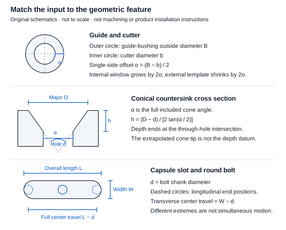
| Quantity | Enter this | Do not substitute |
|---|---|---|
| Bushing diameter | Outside diameter of the circular guide | Bushing bore diameter |
| Countersink angle | Full included cone angle | Half-angle used inside the formula |
| Slot length | Outside end to outside end | Distance between semicircle centers |
| Thread pitch | Axial spacing between adjacent threads | Lead of a multiple-start thread |
| Feed per revolution | Total axial feed in one turn | Feed per tooth or feed per minute |
Size an internal or external router template
In router template offset, select the mode, common dimension unit, guide outside diameter, cutter diameter, and required finished width and height. The guide diameter must exceed the cutter diameter, and all dimensions must be positive. The model assumes concentric circular tooling following straight template edges.
Example inputs: guide 5/8 in, cutter 3/8 in, finished envelope 1 × 2.25 in.
Single-edge offset = (0.625 − 0.375)/2 = 0.125 in = 3.175 mm
An overall width spans two offsets. For an internal window, add 2 × 0.125 = 0.25 in to each finished dimension: 1.250 × 2.500 in. For an external template, subtract 0.25 in: 0.750 × 2.000 in. External dimensions must remain positive. The result does not check runout, guide height, corner radii, or tool compatibility.
Find conical countersink depth
In countersink depth, choose countersink mode and enter top-surface major diameter D, coaxial through-hole diameter d, and full included angle α. The model requires D > d > 0 and 0° < α < 180°.
Axial depth = (D − d)/[2 tan(α/2)]
Example inputs: D 0.5 in, d 0.25 in, α 90°.
Depth = (0.5 − 0.25)/(2 × tan 45°) = 0.125 in = 3.175 mm
Displayed result: 0.125 in / 3.175 mm. This is the depth to the cone’s intersection with the through hole, not a screw-head specification. The same tool’s ideal drill-point mode replaces d with zero and adds the point height to a supplied full-diameter depth. It omits nonconical web geometry, approach, and breakthrough allowances.
Distinguish slot-center separation from bolt travel
In slot travel, enter overall capsule-slot length L, width W, and round bolt shank diameter B. All must be positive, with L ≥ W and B ≤ W.
Example inputs: L 1 in, W 3/8 in, B 1/4 in.
| Result | Calculation | Inches | Millimeters |
|---|---|---|---|
| Semicircle-center separation | L − W | 0.625 | 15.875 |
| Full longitudinal bolt-center travel | L − B | 0.750 | 19.050 |
| Full transverse bolt-center travel | W − B | 0.125 | 3.175 |
These are separate extreme-to-extreme ranges. A bolt cannot necessarily reach both the longitudinal and transverse extremes at the same time. Washers, bearing area, strength, and permitted adjustment remain separate checks.
Keep thread-hole size and thread travel separate
The tap drill calculator needs the thread family, cutting or forming process, basic major diameter, TPI or axial pitch, and desired thread percentage. The percentage must be greater than zero and no more than 100; it is not joint strength or engagement length. A formula result must be positive.
For a hypothetical 0.25 in, 20 TPI, 75% UNC/UNF cutting case, Guhring’s formula gives:
Hole = 0.25 − 0.01299 × 75/20 = 0.2012875 in = 5.1127025 mm
Displayed result: 0.201 in / 5.113 mm, with the unrounded formula result retained. This does not select a commercial drill. Forming and metric formulas use different coefficients; changing thread family is not just changing units.
For thread lead and travel, enter TPI or pitch, the verified whole-number start count 1–100, and nonnegative revolutions. With 20 TPI, one start, and 0.25 turn:
Pitch = 1/20 = 0.05 in; lead = 0.05 × 1 = 0.05 in/turn
Ideal travel = 0.05 × 0.25 = 0.0125 in = 0.3175 mm
Three-decimal displays are 0.013 in / 0.318 mm. Use the unrounded travel for further work. Backlash and product adjustment limits are absent.
Convert supplied drilling parameters
In drilling speed and feed, supply positive diameter, surface speed, and axial feed per revolution. Enter nonnegative total feed travel. Dimension units and surface-speed units are selected independently.
Example inputs: diameter 0.5 in, speed 100 SFM, feed 0.005 in/rev, travel 1 in.
rpm = 12 × 100/(π × 0.5) ≈ 763.9437268
Axial feed = rpm × 0.005 ≈ 3.8197186 in/min
Ideal time = 1/3.8197186… × 60 ≈ 15.7079633 s
Displayed results: 763.944 rpm, 3.820 in/min, and 15.708 s. Retain full precision between steps. Constant-feed time excludes setup, pecking, retraction, and other cycle operations.
Conclusion and sources
Record each result with its actual drawing, tooling data, input reference, and unrounded values. Three-decimal display does not create a machining tolerance. Lee Valley explains guide offsets; Guhring, Common Formulas for Tapping, printed p. 240 supplies the tap-hole coefficient; Rocky Mountain Twist explains speed/feed relationships. Cone and slot formulas follow elementary geometry, with exact length conversion. Actual materials, tool instructions, remaining material, and assembly restrictions still determine whether an operation is appropriate.