An ideal circuit calculator is useful only when its topology matches the actual circuit. A label such as “DEOL,” “LED indicator,” or “timer” does not identify the internal component arrangement. Compare nodes, resistor placement, contacts, initial conditions, and switch-off paths before selecting a model.
Match the schematic before the component values
Use the ideal topology atlas to identify the modeled circuit. A bare-LED branch differs from a complete rated indicator. A first-order RC node differs from a commercial timer. A source-free RL loop differs from a coil protected by a diode or clamp.
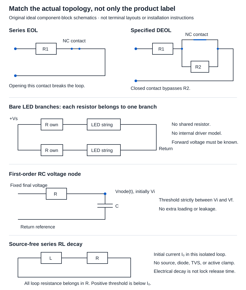
| Circuit feature | Calculator | Required condition |
|---|---|---|
| One of the stated resistor/contact arrangements | EOL / DEOL resistance | Exact topology and ideal contact states match |
| Identical bare-LED strings with separate resistors | LED series resistor | Forward voltage and branch current are supplied |
| First-order voltage approaching a fixed final value | RC threshold time | Threshold strictly between distinct initial and final voltages |
| Isolated inductor/resistor loop after source removal | Ideal RL decay | No source, diode, TVS, or active clamp in the decay path |
Calculate the stated supervision circuit’s resistance
The EOL model places R1 in series with a normally closed alarm contact. The DEOL model places R1 in series with the parallel combination of that contact and R2. Closed wires and contacts have ideal zero resistance.
Select EOL or DEOL and enter hypothetical R1 = 1000 Ω. For DEOL also enter R2 = 2000 Ω. Both required resistors must be positive decimal values.
| Physical state | EOL calculation/result | DEOL calculation/result |
|---|---|---|
| Alarm contact closed | R1 = 1000.000 Ω | Contact bypasses R2: 1000.000 Ω |
| Alarm contact open | Series path broken: open circuit | R1 + R2 = 1000 + 2000 = 3000.000 Ω |
| Series wire or series tamper open | Open circuit | Open circuit |
| Ideal short directly across panel terminals | 0 Ω | 0 Ω |
Opening the alarm contact and breaking a series wire produce the same ideal resistance in the EOL topology. A short elsewhere can bypass a different combination of components; the zero-ohm row specifically means a short across the panel terminals.
These are series/parallel resistance results, not controller recognition thresholds. Check actual schematic revision, resistor tolerances, cable effects, and recognized resistance bands separately.
Establish whether the LED is bare or already controlled
For the LED tool, enter hypothetical source 12 V, forward voltage 2 V per LED, one LED per string, 10 mA branch current, and one parallel branch. Every branch has its own series resistor.
Resistor voltage = source − count × forward voltage = 12 − 1 × 2 = 10 V
Branch current = 10 mA = 0.01 A
Theoretical resistance = 10/0.01 = 1000.000 Ω
Resistor dissipation = 10 × 0.01 = 0.100 W
Source voltage must exceed the total supplied LED forward voltage. Voltages and branch current must be positive; LED and branch counts must be whole numbers 1–1000.
The result does not select a preferred resistor value or wattage rating. Source extremes, LED variation, temperature, and actual component ratings require separate design information. A complete rated indicator may contain current control already; apply its documentation rather than assuming this bare-LED circuit.
Use an RC threshold strictly between its endpoints
In RC threshold time, enter resistance 1000 Ω, capacitance 1000 µF, initial voltage 0 V, final voltage 10 V, and threshold 5 V.
C = 1000 µF = 0.001 F
Time constant τ = RC = 1000 × 0.001 = 1 s
For the first-order RC relationship:
V(t) = Vf + (Vi − Vf)e^(−t/τ)
t = −τ ln[(Vthreshold − Vf)/(Vi − Vf)]
t = −1 ln[(5 − 10)/(0 − 10)] = ln 2 ≈ 0.693 s
Resistance and capacitance must be positive. Voltage inputs are nonnegative; the threshold must lie strictly between distinct initial and final values, whether rising or falling. Reaching the exact final asymptote has no finite time in this model. Additional loading, leakage, and commercial timer logic are outside it.
Match the complete RL switch-off path
For ideal source-free series RL decay, enter 1 H inductance, 10 Ω total loop resistance, 1 A initial current, and 0.5 A threshold:
Initial energy = LI₀²/2 = 1 × 1²/2 = 0.500 J
Time constant τ = L/R = 1/10 = 0.100 s
Threshold time = τ ln(I₀/Ithreshold) = 0.1 ln 2 ≈ 0.069 s
All four inputs must be positive, and threshold current must be below initial current. This follows the source-free RL decay equation.
A flyback diode, TVS, active clamp, or remaining supply changes the decay circuit. It cannot be represented by choosing an arbitrary resistor. Electrical current decay also does not determine mechanical lock release time, residual magnetism, or an approved suppression method.
Accept a result only within the matching model
Finite displays use three decimal places; logarithmic timing outputs are approximations. Keep full input precision through the calculation. Retain schematic revision, component sources, topology, initial state, threshold, result, and omitted effects together.
If the product circuit or a required value is unknown, obtain the appropriate documentation or analysis before using the tool. When the model does match, use its result for that limited electrical question and verify actual controller behavior and component ratings separately.