A DC source budget is valid only at one electrical boundary. Decide whether the source rail, a converter output rail, or an enclosure heat boundary is being totaled, then count each load once. A converter’s output current cannot be added to its own source current on the same rail.
Draw the rails and name simultaneous states
Record supply voltage, device quantity, current, source or load side, and the state represented by each scenario. The DC boundary and time-accounting record keeps those definitions together.
The DC load budget calculator accepts one positive supply voltage, 1–20 named load rows, and two alternative simultaneous scenarios. Each row has a quantity from 1–1000 and one current for each scenario. The two scenarios are alternatives; do not add them as if they occur at the same time.
| Boundary | Include | Keep separate |
|---|---|---|
| 24 V source rail | Converter input current and devices directly on 24 V | Converter output current on a downstream 12 V rail |
| 12 V converter output | Loads supplied by the converter | 24 V source current unless translated through efficiency |
| Enclosure heat | Power actually dissipated inside the enclosure | Power delivered to an external load |
Use zero only when a device is explicitly off in that scenario. Missing current data is unresolved input, not zero. Startup timing, inrush, reserve, and derating require separate information.
Translate a converter operating point to its source
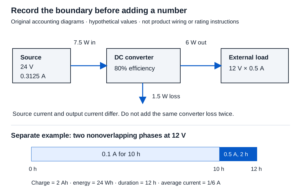
First calculate a known operating point. With hypothetical 12 V output and 0.5 A, the output is:
Pout = V × I = 12 × 0.5 = 6 W
A separate converter calculation with 24 V source and explicitly supplied 80% efficiency gives the source-side requirement. In the converter load calculator, enter source voltage 24, output voltage 12, output current 0.5, and efficiency 80. Both voltages must be positive, current nonnegative, and efficiency greater than 0% and at most 100%.
Pin = Pout / efficiency = 6 / 0.8 = 7.5 W
Iin = Pin / Vsource = 7.5 / 24 = 0.3125 A
Converter loss = Pin − Pout = 1.5 W
The converter-load calculator displays input current as 0.313 A. Keep 0.3125 A when entering the source budget; do not feed the rounded display into another calculation.
For DC Ohm’s law, the same 12 V and 0.5 A operating point has equivalent resistance:
R = V/I = 12/0.5 = 24 Ω
That equivalent resistance describes this operating point. It does not prove an electronic load draws proportional current at another voltage.
Add direct source loads once
Suppose a separate controller draws 0.1 A directly from 24 V in both example states. In the DC load budget, enter supply voltage 24. Name scenario A “Converter operating; controller on” and scenario B “Converter off; controller on.” Enter these two rows, using decimal currents in A:
| Source-side row | Quantity | Scenario A per unit (A) | Scenario B per unit (A) |
|---|---|---|---|
| Converter input | 1 | 0.3125 | 0 |
| Direct controller | 1 | 0.1 | 0.1 |
| Scenario total | 0.4125 A | 0.1 A |
Psource = 24 × 0.4125 = 9.900 W
Scenario A current is 1 × 0.3125 + 1 × 0.1 = 0.4125 A. Its result shows 0.413 A and 9.900 W after three-decimal display rounding. Scenario B shows 0.100 A / 2.400 W. Here zero explicitly means the converter is off; it does not estimate the standby consumption of an energized converter.
Do not add the converter’s 0.5 A output or 1.5 W loss again: its source input already represents both delivered power and loss.
Check a PoE allocation pool at the PSE boundary
For a switch or injector, a connected device’s present power draw can differ from the power allocated to its port. The PoE allocation budget calculator checks an explicit static plan: each allocation must cover the supplied PSE-side allowance and stay within its port cap, while all allocations together stay within one available PoE output pool. A large remaining pool cannot fix an undersized port allocation.
Use the actual equipment configuration and budgeting policy. Meraki’s PoE budgeting documentation distinguishes requested-power and consumption-based policies for different products and modes. A device-side watt figure or an AC adapter rating does not by itself establish the PSE allocation or output budget. Keep those source records with the plan; negotiation and startup need separate verification.
Keep enclosure heat on its own boundary
If the controller dissipates 2.4 W inside the enclosure, the converter is also inside, and the 6 W output load is outside, modeled internal heat is:
Qheat = controller loss + converter loss = 2.4 + 1.5 = 3.900 W
In the enclosure heat-loss calculator, enter 1,2.4 in the direct-loss list and 1,6,80 in the converter list: quantity, output watts, efficiency percent. Do not list the converter loss again as direct loss. Electrical power and energy supports this bookkeeping; it does not predict cabinet temperature or product ratings.
Complete the source check with actual data
Retain the rail drawing, original current values, efficiency source, simultaneous-state descriptions, and calculations. Then verify source voltage range, converter limits, direct-load conditions, startup behavior, protection, thermal conditions, and any applicable derating with the actual equipment information.
This budget closes a stated electrical boundary. It does not choose a power supply, invent a reserve percentage, or establish that all devices start simultaneously or operate safely.