A useful door survey separates the frame outline, the usable opening, the intended gaps, and the floor elevations. These measurements concern the same assembly but use different references. This sheet explains how to collect them and choose a calculation without treating an out-of-square frame, a floor high point, and a door-edge bevel as the same problem.
The examples use hypothetical dimensions and supplied gaps. They do not specify a permissible undercut, fabrication size, or modification to a rated assembly.
Establish the survey references
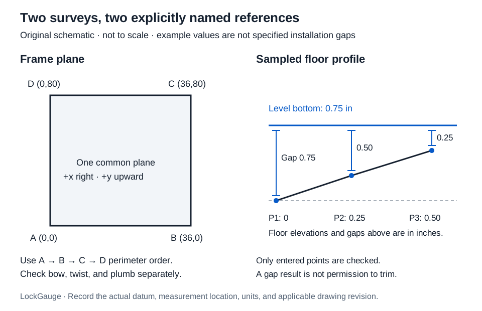
- Identify the actual frame opening and measurement plane, including the stops or rabbets that define its edges.
- Mark an origin and positive x and y directions. Use one unit for all coordinates in a calculation.
- Identify four physical corner points in perimeter order. Record intermediate edge observations separately.
- For floor samples, establish a common vertical datum and record where each sample lies along the proposed door path.
- Obtain the applicable drawing and gap requirements before subtracting any gaps from an opening dimension.
A nominal frame size is not automatically the usable opening. Four corners describe a planar outline, not whether the frame is plumb, twisted, or straight between those corners.
Check the frame outline before assuming a rectangle
The frame geometry calculator accepts exactly four distinct corners of a convex outline in perimeter order. Enter one x, y pair per line and describe the common plane and axes. Crossed, concave, or collinear outlines are unsupported.
For a hypothetical rectangular opening, enter these inch coordinates:
| Corner | x (in) | y (in) | Following side |
|---|---|---|---|
| A | 0 | 0 | AB = 36 in |
| B | 36 | 0 | BC = 80 in |
| C | 36 | 80 | CD = 36 in |
| D | 0 | 80 | DA = 80 in |
Both diagonals are √(36² + 80²) = √7696 ≈ 87.7268488 in, displayed as 87.727 in. Each corner angle is 90.000°, so the largest departure from a right angle is 0.000°. The right-angle results follow from the perpendicular sides, not simply from the equal diagonals. Equal diagonals in another quadrilateral do not by themselves prove a rectangle.
Work from an opening to a single leaf
In door leaf dimensions, choose a single leaf or two equal leaves. Enter the opening width and height and each required gap. Gaps must be nonnegative, and both resulting leaf dimensions must remain positive. The equal-pair mode also subtracts the meeting gap before dividing the available width by two.
Example inputs: single leaf; opening 36 × 80 in; left and right gaps 0.125 in each; top gap 0.125 in; bottom gap 0.75 in.
Leaf width = 36 − 0.125 − 0.125 = 35.750 in
Leaf height = 80 − 0.125 − 0.75 = 79.125 in
The exact millimeter dimensions are 908.050 × 2009.775 mm. These supplied gaps are example assumptions, not U.S. defaults. Stops, seals, thresholds, bevels, and hardware can change which physical references are appropriate.
Compare a level bottom with sampled floor elevations
The bottom-gap profile calculator subtracts each floor elevation from one fixed, level bottom elevation. Enter 1–50 floor elevations, one per line, in the same unit as the bottom and required minimum gap. Sample only locations that you can identify again.
Example inputs: bottom elevation 0.75 in; floor elevations 0, 0.25, 0.50 in; required minimum gap 0.50 in.
| Sample | Floor elevation (in) | Current gap: 0.75 minus elevation (in) | Meets the supplied 0.50 in minimum? |
|---|---|---|---|
| P1 | 0.000 | 0.750 | Yes |
| P2 | 0.250 | 0.500 | Yes, at the boundary |
| P3 | 0.500 | 0.250 | No |
Required level bottom = highest sampled floor + required gap = 0.50 + 0.50 = 1.000 in
Required increase = 1.000 − 0.750 = 0.250 in
This is a theoretical change in elevation, not an instruction to trim 0.250 in from a door. Unmeasured high points, floor variation across the leaf thickness, and nonlevel door bottoms remain outside the sampled model.
Keep bevel and temperature calculations separate
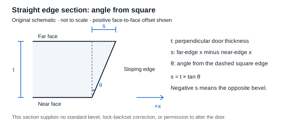
For edge bevel geometry, supply a positive perpendicular thickness and either a signed offset or an angle strictly between −90° and 90°. The relationships are offset = thickness × tan(angle) and sloped edge length = thickness/cos(angle). Identify the near and far faces before interpreting the sign.
For free thermal change, retain each dimension’s reference temperature, its own temperature change, and a supported coefficient per °C. The tool uses change = original length × coefficient × temperature change and reports frame change minus door change. It does not predict an installed gap in a restrained or layered assembly.
Conclusion and calculation basis
Use the survey to establish the geometry first, then apply the tool that answers the specific question. Retain original inputs and round only final displays, normally to three decimal places. These calculations use coordinate geometry, dimension chains, and exact unit definitions; none supplies product gap limits or permission to alter an assembly.